Spring adjusting mechanism

A spring adjustment and frame adjustment technology, which is applied in metal processing, metal processing equipment, manufacturing tools, etc., can solve the problems of reduced production efficiency of valve spring and valve terminal assembly, cumbersome assembly process composition, etc., to simplify the production process and improve production efficiency effect

Active Publication Date: 2019-08-09
慕贝尔汽车部件(太仓)有限公司
View PDF9 Cites 0 Cited by
  • Summary
  • Abstract
  • Description
  • Claims
  • Application Information

AI Technical Summary

Problems solved by technology

[0002] like Figure 10 As shown, the valve spring on the automobile piston needs to be installed and used in conjunction with the valve terminal, that is, during production, the valve terminal needs to be installed on the valve spring, and the valve spring is conical. The valve spring has two ends, and the valve terminal is installed on the valve. On the big end of the spring, in the traditional valve spring assembly production process, the big end of the valve spring cannot be adjusted to correspond to the valve terminal, and it is often necessary to adjust it before feeding, which makes the assembly process more cumbersome. The valve spring and the valve terminal assembly productivity reduction

Method used


Image

  • Spring adjusting mechanism
  • Spring adjusting mechanism
  • Spring adjusting mechanism

Examples


Embodiment Construction

[0027] Embodiments of the present invention are described in detail below, examples of which are shown in the drawings, wherein the same or similar reference numerals designate the same or similar elements or elements having the same or similar functions throughout. The embodiments described below by referring to the figures are exemplary only for explaining the present invention and should not be construed as limiting the present invention. On the contrary, the embodiments of the present invention include all changes, modifications and equivalents coming within the spirit and scope of the appended claims.

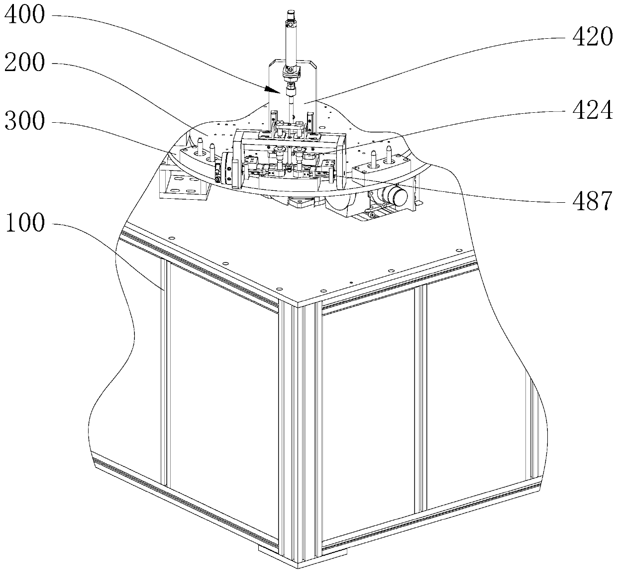
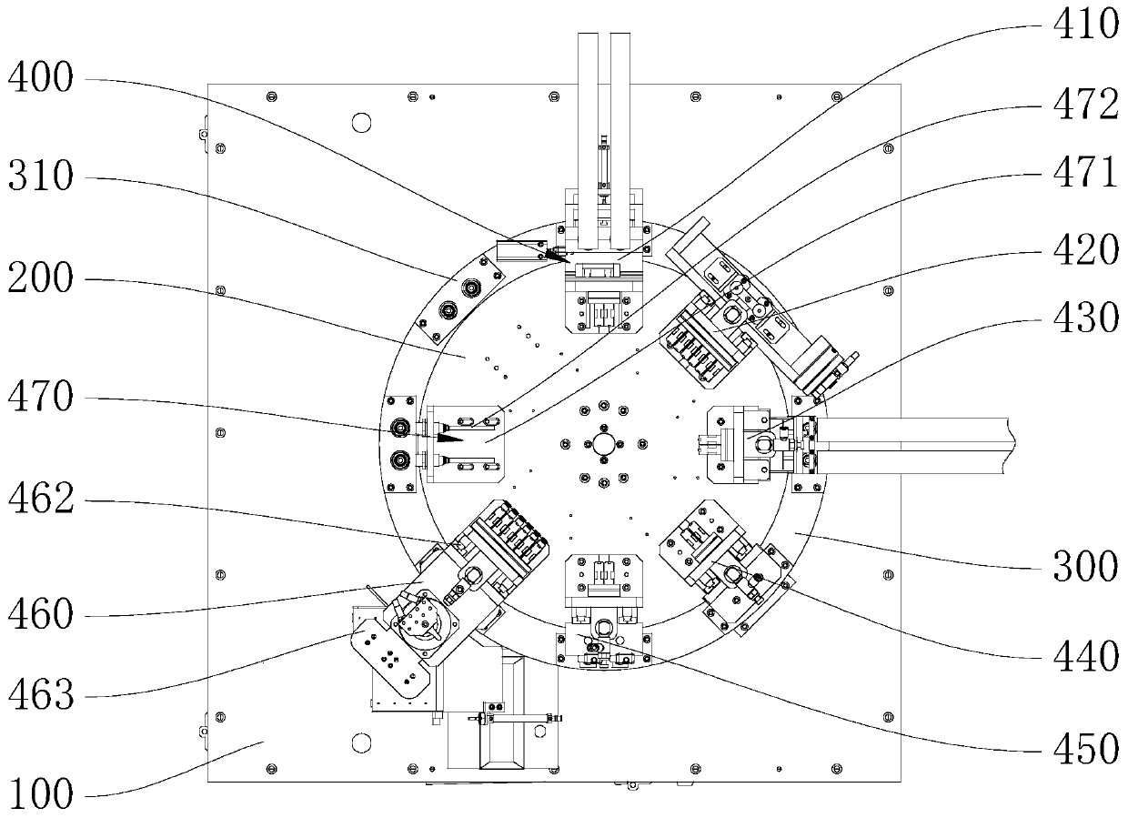
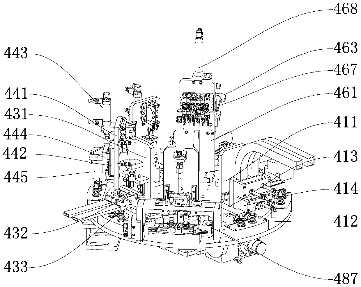
[0028] Such as Figure 1 to Figure 9 As shown, a spring assembly machine is used to assemble the valve spring 101 and the valve terminal 102, including the frame 100, the fixed plate 200, the rotating plate 300 and the assembly assembly 400, the fixed plate 200 is fixedly installed on the frame 100, and the rotating plate 300 can be It is mounted between the frame 100 and...


PUM


Abstract

The invention provides a spring adjusting mechanism. The spring adjusting mechanism comprises a push cylinder, an adjusting frame, touch sensors and adjusting clamping jaws. The adjusting frame is installed on a cylinder piston shaft in a slidable mode, the touch sensors are arranged in the adjusting frame, and the adjusting clamping jaws are installed in the adjusting frame in a rotatable mode. The touch sensors are arranged in the mode of corresponding to springs. A driving assembly is installed on the adjusting frame and drives the touch sensors to slide relative to the adjusting frame. Thetouch sensors are electrically connected to the adjusting clamping jaws. After the adjusting clamping jaws ascend along with the adjusting frame in a clamping state, the adjusting clamping jaws rotate relative to the adjusting frame, the directions of the springs are judged by the touch sensors, the adjusting clamping jaws in the adjusting frame are utilized to clamp the springs and conduct rotation and directional adjustment, and therefore the directions of the springs can be same.

Description

technical field [0001] The invention relates to the technical field of spring assembly, in particular to a spring adjustment mechanism. Background technique [0002] Such as Figure 10 As shown, the valve spring on the automobile piston needs to be installed and used in conjunction with the valve terminal, that is, during production, the valve terminal needs to be installed on the valve spring, and the valve spring is conical. The valve spring has two ends, and the valve terminal is installed on the valve. On the big end of the spring, in the traditional valve spring assembly production process, the big end of the valve spring cannot be adjusted to correspond to the valve terminal, and it is often necessary to adjust it before feeding, which makes the assembly process more cumbersome. The valve spring and the valve terminal The assembly production efficiency is reduced. Contents of the invention [0003] Based on the above technical problems, the present invention provide...

Claims


Application Information

Patent Timeline
Patent Type & Authority Applications(China)
IPC IPC(8): B23P19/00B23P19/04
CPCB23P19/00B23P19/04B23P19/048
Inventor 王铁强
Owner 慕贝尔汽车部件(太仓)有限公司
Why Eureka
Try Eureka