Eureka AIR delivers breakthrough ideas for toughest innovation challenges, trusted by R&D personnel around the world.

Underwater riprap device

A box and shaft technology, applied in construction, infrastructure engineering, etc., can solve the problems of limited volume of grabbing buckets, difficult control of construction accuracy, and broken life of net bags, and achieve long service life, large adjustment range, and transportation efficiency. high effect

Active Publication Date: 2019-08-06
CHINA HARBOUR ENGINEERING
View PDF6 Cites 2 Cited by
  • Summary
  • Abstract
  • Description
  • Claims
  • Application Information

AI Technical Summary

Problems solved by technology

[0002] In the construction of breakwater protection, some large stones are often added to increase the strength of the breakwater, especially in deep waters. During the construction process, the traditional way of adding large stones is to transport and throw them with net bags or grab buckets. For riprapping stones, it is difficult to control the construction accuracy by using a net bag, and the broken net bag has a short service life; using a grab bucket for riprap, the volume of the grab bucket is limited, and the construction efficiency is low. Therefore, a design with high construction accuracy and high construction efficiency, Long-life ripraps make a lot of sense

Method used

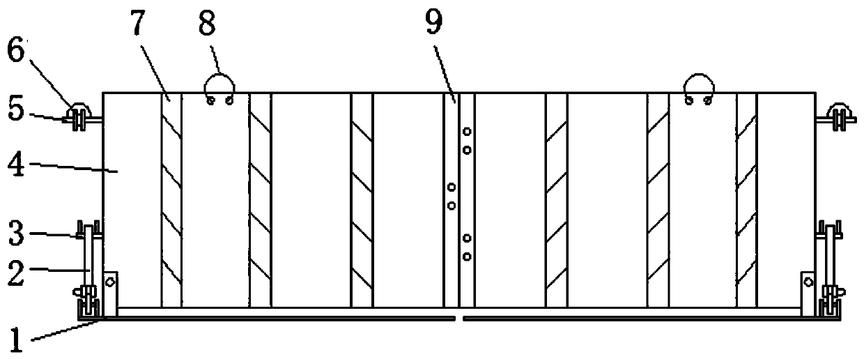
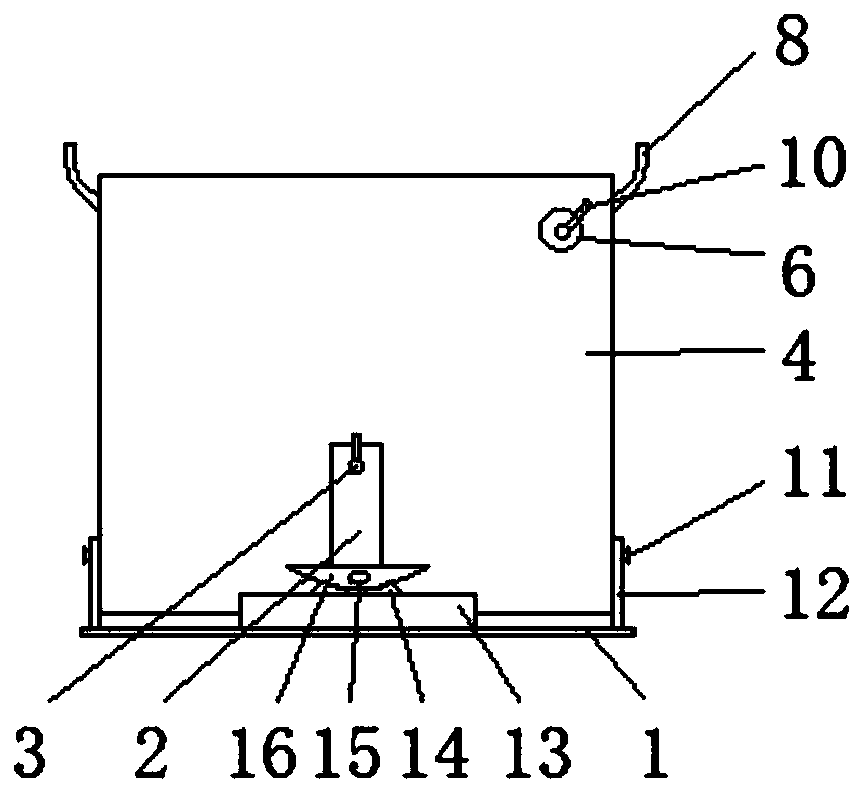
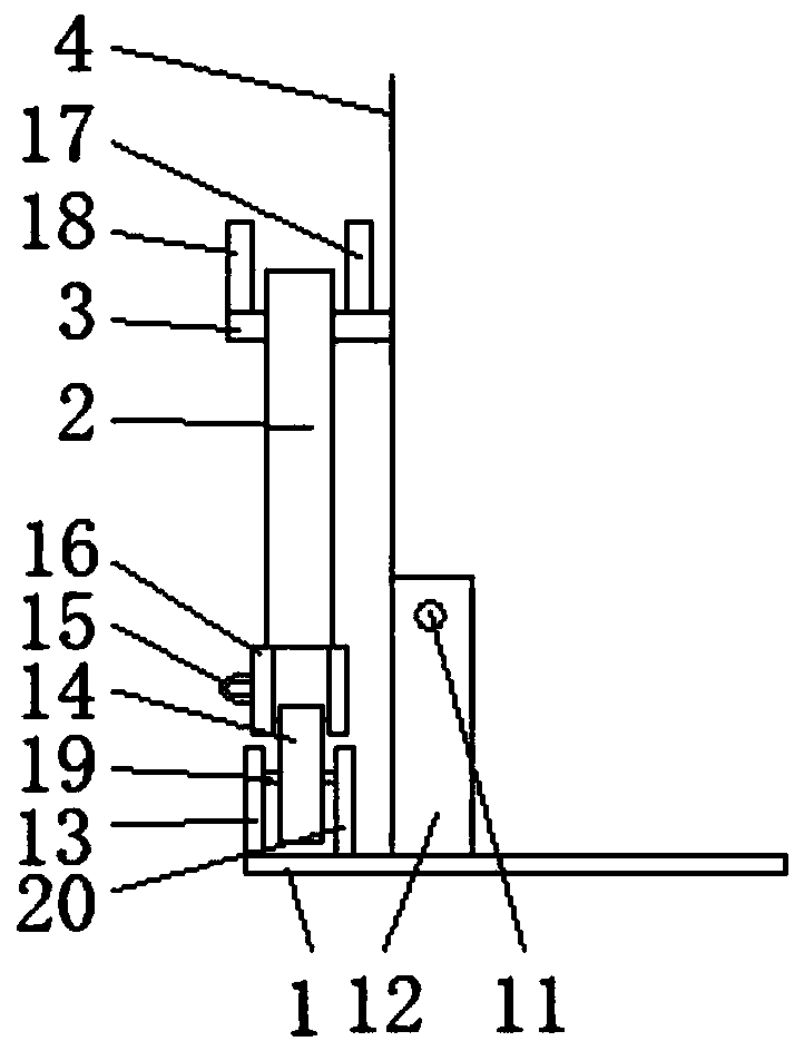

Image

  • Underwater riprap device
  • Underwater riprap device
  • Underwater riprap device

Examples


Embodiment Construction

[0023] The present invention will be further described in detail below with reference to the accompanying drawings, so that those skilled in the art can implement it with reference to the text of the description.

[0024] It should be understood that terms such as "having", "including" and "including" used herein do not exclude the presence or addition of one or more other elements or combinations thereof.

[0025] It should be noted that the experimental methods described in the following embodiments are conventional methods unless otherwise specified. The reagents and materials, unless otherwise specified, can be obtained from commercial sources; in the description of the present invention, It should be noted that, unless otherwise clearly specified and limited, the terms "installation", "connection", and "setting" should be understood in a broad sense, for example, it can be fixed connection, setting, or detachable connection, setting, or Connect and set in one piece. For those...


PUM


Abstract

The invention discloses an underwater riprap device.The underwater riprap devicecomprises a cargo box, asupport assembly, and afixing assembly, wherein the cargo box is composed of a pair of box bodies, the box bodiesare opened at the top, the bottom, and the opposite sides and connected by front and rear connecting plates, hang rings are arranged on the box bodies, and the bottomsof the box bodiesarerotatably connected with a pair of bottom plates; the support assembly comprises a first support plate and a second support plate, the first support plate and the second support plate arearrangedoutsides the side walls of the box bodies and connected with the bottom plates, and a roller is arranged between the first support plate and the second support plate;the fixing assembly comprises a third rotating shaft, guide pulleys, and a rotating plate, the third rotating shaft and the guide pulleys are arranged on the side walls of the box bodies,the rotating plate can rotatably sleeve the third rotating shaft, the third rotating shaft is horizontally arranged and positioned higher than a second rotating shaft, a circular arc-shaped sliding groove is formed in the bottom end of the rotating plate, the roller is in contact with a track in the sliding groove and can slide along the track in the sliding groove,a pull ring is arranged in the sliding groove, a pull rope is arranged in the pull ring, the guide pulleysare rotatably arranged on the side walls of the box bodiesand located obliquely above the third rotating shaft, and the pull rope moves through the guide pulleys. The underwater riprap deviceis high in transportation efficiency and longin service life.

Description

Technical field [0001] The invention relates to the technical field of underwater engineering construction equipment, in particular to an underwater rock dumping device. Background technique [0002] In the construction of the breakwater protection surface, some large rocks are often added to increase the strength of the breakwater, especially in deep waters. The traditional method of adding large rocks during the construction process is a net bag or grab bucket for transportation and throwing. Stones are thrown in net bags, the construction accuracy is difficult to control, and the life of the net bags is short. The use of grabs for stone dumping has limited volume and low construction efficiency. Therefore, a design with high construction accuracy and high construction efficiency is designed. The long-life stone dumping device is of great significance. Summary of the invention [0003] An object of the present invention is to solve at least the above-mentioned problems and to p...

Claims


Application Information

Patent Timeline
IPC IPC(8): E02D15/10
CPCE02D15/10
Inventor 陶然史春岩熊韬黄睿奕乐砾
Owner CHINA HARBOUR ENGINEERING
Why Eureka
Eureka Blog
Learn More