System and method for preparing plasma activated water for sterilization in cavity
A plasma and cold plasma technology, applied in the field of plasma sterilization and disinfection, can solve problems such as safety risks, and achieve the effect of low system use cost and strong sterilization ability
- Summary
- Abstract
- Description
- Claims
- Application Information
AI Technical Summary
Problems solved by technology
Method used
Image
Examples
Embodiment 1
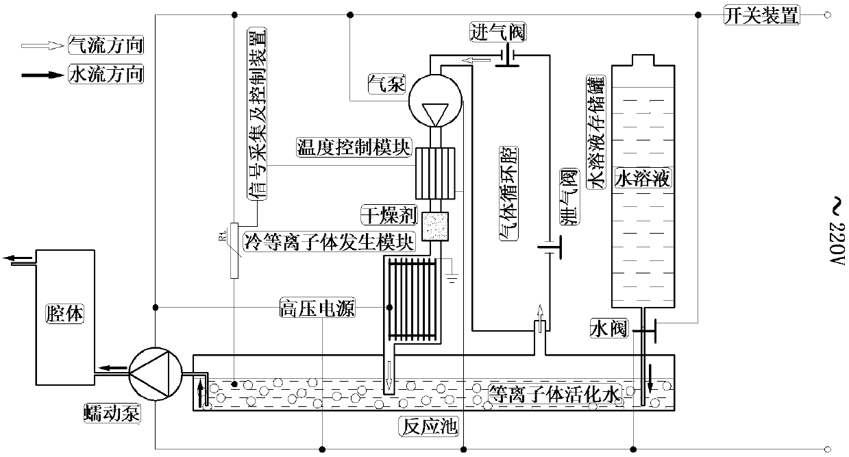
[0028] Such as figure 1 As shown, a system for preparing plasma-activated water for in-cavity sterilization includes a switch device, an aqueous solution storage tank, a water valve, an aqueous solution reaction tank, a gas circulation chamber, an air pump, a temperature control module, a temperature sensor, and a signal acquisition And control module, desiccant, cold plasma generation module and peristaltic pump.
[0029] The entire system is externally connected to a working power supply, which can provide a rated working voltage of 220V, and a switch device is provided between the system and the external working power supply. When the system needs to enter the working state, the switching device can be closed; when the system exits the working state, the switch The device can be disconnected.
[0030] The top of the aqueous solution storage tank is provided with a water injection hole for injecting the aqueous solution into the tank. The water injection hole is not complet...
Embodiment 2
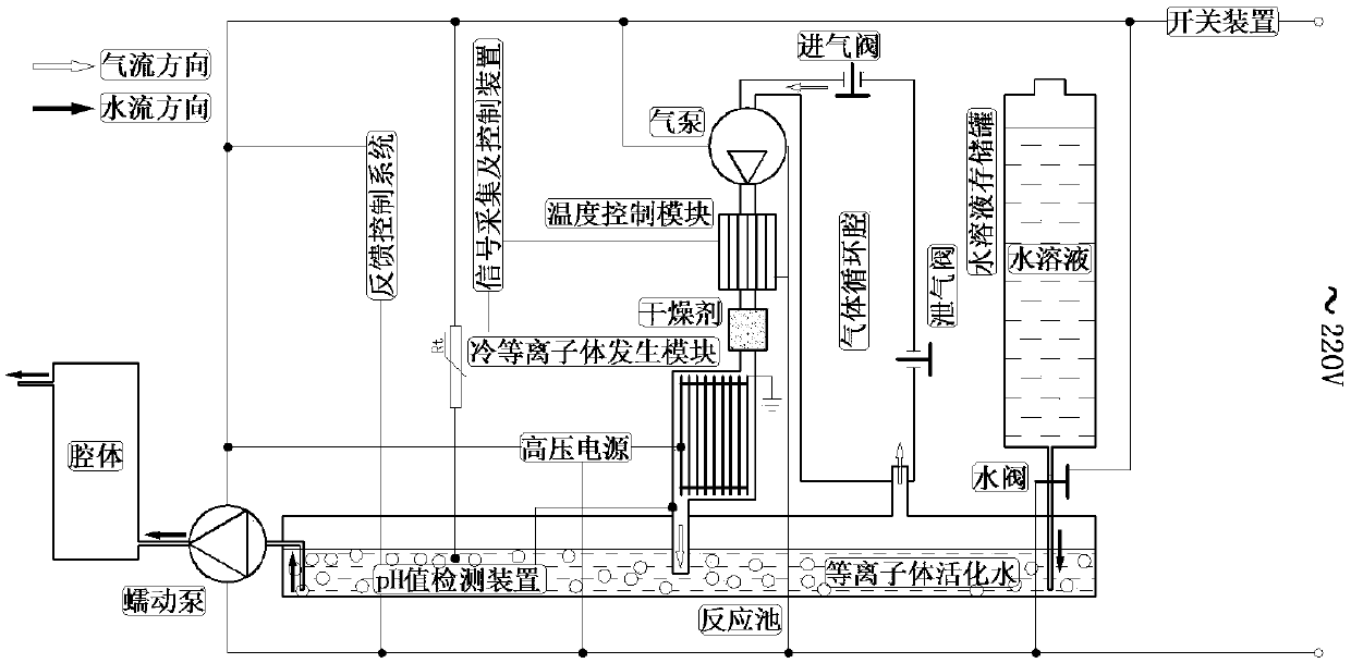
[0037] Compared with embodiment 1, present embodiment has installed pH value detecting device in aqueous solution reaction tank, as figure 2 shown. Through the detection results of the pH value of the aqueous solution, the working states of the connected peristaltic pump and the cold plasma generation module are respectively controlled through a feedback control system. When the pH value of the aqueous solution in the aqueous solution reaction pool is between 3-6, the sterilization ability is the strongest, the peristaltic pump works, the discharge of the cold plasma generation module is weakened, and the number of cold plasmas is reduced; when the aqueous solution in the aqueous solution reaction pool When the pH value is greater than 6, the sterilizing ability is the weakest, the peristaltic pump stops working, the discharge of the cold plasma generation module is enhanced, and the amount of cold plasma generated increases.
Embodiment 3
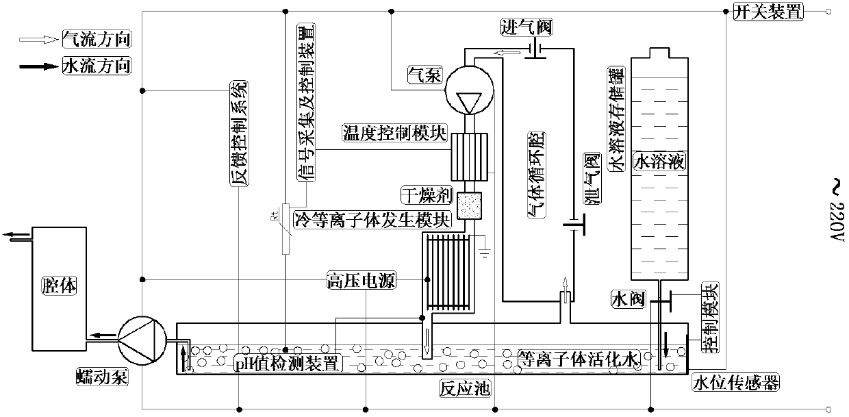
[0039] Compared with embodiment 2, this embodiment increases the water level sensor and control module, such as image 3shown. The water level sensor is installed in the aqueous solution reaction tank and is connected with the water valve through the control module to monitor the change of the water level in the reaction tank. When the liquid level in the aqueous solution reaction tank falls below the threshold, the water level sensor feeds back a signal to the control module, and the control module can control the opening of the water valve, and the aqueous solution is injected into the aqueous solution reaction tank.
PUM
 Abstract
Description
Claims
Application Information
 - R&D
- Intellectual Property
- Life Sciences
- Materials
- Tech Scout
- Unparalleled Data Quality
- Higher Quality Content
- 60% Fewer Hallucinations
Browse by: Latest US Patents, China's latest patents, Technical Efficacy Thesaurus, Application Domain, Technology Topic, Popular Technical Reports.
© 2025 PatSnap. All rights reserved.Legal|Privacy policy|Modern Slavery Act Transparency Statement|Sitemap|About US| Contact US: help@patsnap.com


