
Circular section pressure pipe annular anti-throwing limiting device and method thereof

A technology of pressure pipelines and restricting devices, which is applied in the direction of pipe components, pipes/pipe joints/fittings, mechanical equipment, etc., can solve problems such as the inability to accurately predict the direction of slamming, and achieve large market application and promotion value, convenient use, and excellent structure reasonable effect

Pending Publication Date: 2019-08-02
JIANGSU HUITONG PIPELINE EQUIP CO LTD
View PDF0 Cites 1 Cited by
  • Summary
  • Abstract
  • Description
  • Claims
  • Application Information

AI Technical Summary

Problems solved by technology

Since the support of the pipeline varies greatly, the direction of the swing cannot be accurately predicted when the swing occurs. Therefore, a device that can generate anti-swing restrictions in any direction within the 360-degree range of the outer circumference of the pipeline is needed to meet the engineering safety requirements.

Method used


Image

  • Circular section pressure pipe annular anti-throwing limiting device and method thereof
  • Circular section pressure pipe annular anti-throwing limiting device and method thereof

Examples


Embodiment Construction

[0024] The technical solutions in the examples of the present invention will be described in detail below in conjunction with the accompanying drawings in the examples of the present invention.

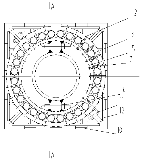
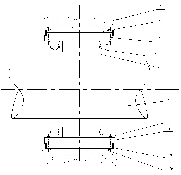
[0025] A ring-shaped anti-swing limiting device for pressure pipes with circular cross-sections, comprising a ring sleeve, which includes an inner ring 5 and an outer ring 2, the outer ring 2 is sleeved outside the inner ring 5, and a gap between the inner ring 5 and the outer ring 2 is formed Annular chamber.

[0026] A circle of flattened energy-absorbing columns 3 is arranged in the annular chamber, and the flattened energy-absorbing pillars 3 are close to the cavity wall of the annular chamber. An elongated energy-absorbing rod 7 is arranged between adjacent flattened energy-absorbing pillars 3 and stretched. One end of the long energy-absorbing rod 7 is fixed to the inner ring 5 and the other end is fixed to the outer ring 2. A first annular guard plate 8 is installed at both axial e...


PUM


Abstract

The invention relates to a circular section pressure pipe annular anti-throwing limiting device and a method thereof. The device comprises an annular sleeve; the annular sleeve comprises an inner ringand an outer ring; the outer ring sleeves the inner ring; a gap between the inner ring and the outer ring forms an annular cavity; a lap of flattening energy absorption columns is arranged in the annular cavity; the flattening energy absorption columns are tightly bonded on the wall of the annular cavity; lengthening energy absorption rods are arranged between the adjacent flattening energy absorption columns; one ends of the lengthening energy absorption rods are fixed with the inner ring, and the other ends are fixed with the outer ring; first annular protecting plates are arranged at two axial ends of the inner ring; second annular protecting plates are arranged at two axial ends of the outer ring; an angle frame connected with the outer ring is arranged in a cavity between the outer ring of the annular sleeve and a building bearing structure; and a gap among the outer ring, the angle frame and the building bearing structure is filled with a wedged cushion plate set. Through the device, when pressure pipes are thrown in any direction, the throwing power energy can be absorbed by plastic deformation of part of the flattening energy absorption columns and the lengthening energy absorption rods.

Description

Technical field [0001] The invention relates to a ring-shaped anti-throwing limiting device and a method for a pressure pipe with a circular section, which is used to prevent secondary disasters caused by a large-scale throwing blow after the pressure pipe is broken, and belongs to the technical field of pressure pipe design anti-throwing limit design. Background technique [0002] Pressure pipelines usually need to be welded to form a piping system, and the welds will suddenly fracture, and high-pressure fluid will spray from the fracture, causing the fractured pipeline to shake substantially, which will cause serious secondary disasters. This is never allowed in the high temperature and high pressure pipelines of nuclear power plants. Therefore, it is necessary to install an anti-swing limiting device near the pipe weld to restrict the swing after the pipe is broken in a small range. Because the pipe supports are very different, the whistling direction when whistling occurs ca...

Claims


Application Information

Patent Timeline
Patent Type & Authority Applications(China)
IPC IPC(8): F16L55/02
CPCF16L55/02
Inventor 李化沈重光高海琴杨杰刘祖鹏许燕
Owner JIANGSU HUITONG PIPELINE EQUIP CO LTD
Learn More