
Air valve in a ventilation and air conditioning system

A technology of air conditioning system and air valve, which is applied in the direction of lift valve, valve device, mechanical equipment, etc., to achieve the effect of reducing turbulent dissipation rate, reducing local resistance and good conformity

Active Publication Date: 2021-01-08
XI'AN UNIVERSITY OF ARCHITECTURE AND TECHNOLOGY
View PDF3 Cites 0 Cited by
  • Summary
  • Abstract
  • Description
  • Claims
  • Application Information

AI Technical Summary

Problems solved by technology

[0003] At present, there are many studies on the resistance reduction of local components such as tees, elbows, and variable diameters, and less attention is paid to local components such as valves. The only research is only focused on the resistance of the damper under different opening states. characteristics, but the research on the problem of drag reduction under the fully open state of the air valve is basically blank

Method used


Image

  • Air valve in a ventilation and air conditioning system
  • Air valve in a ventilation and air conditioning system
  • Air valve in a ventilation and air conditioning system

Examples


Embodiment 1

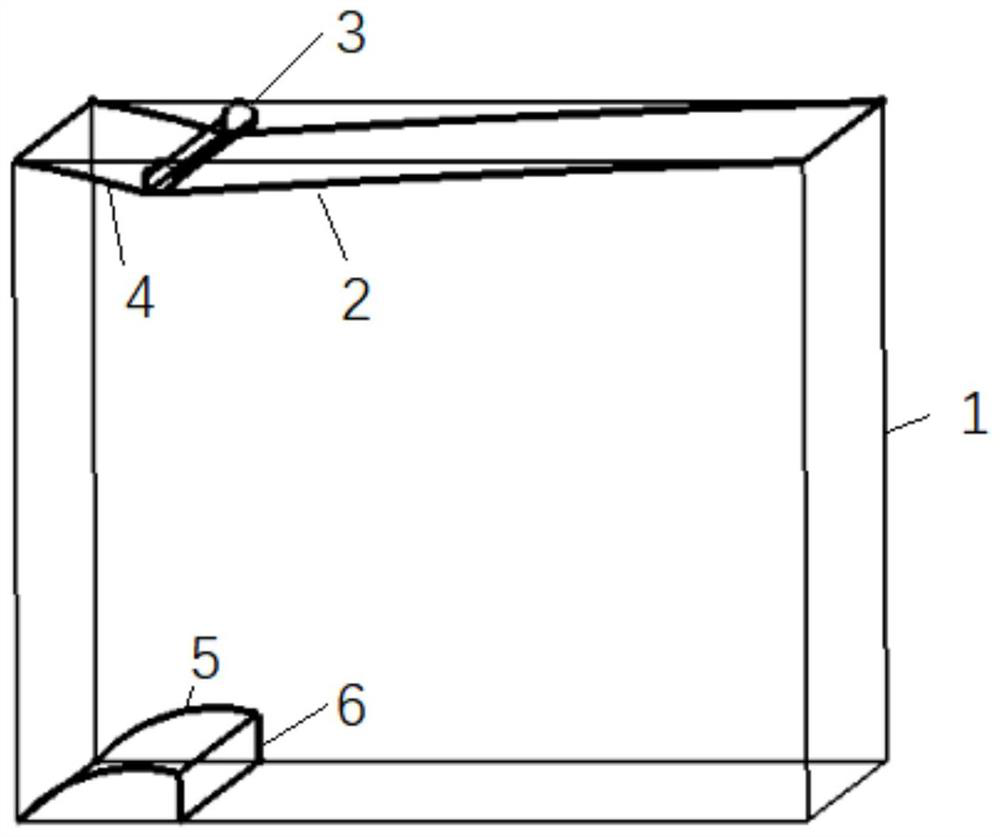
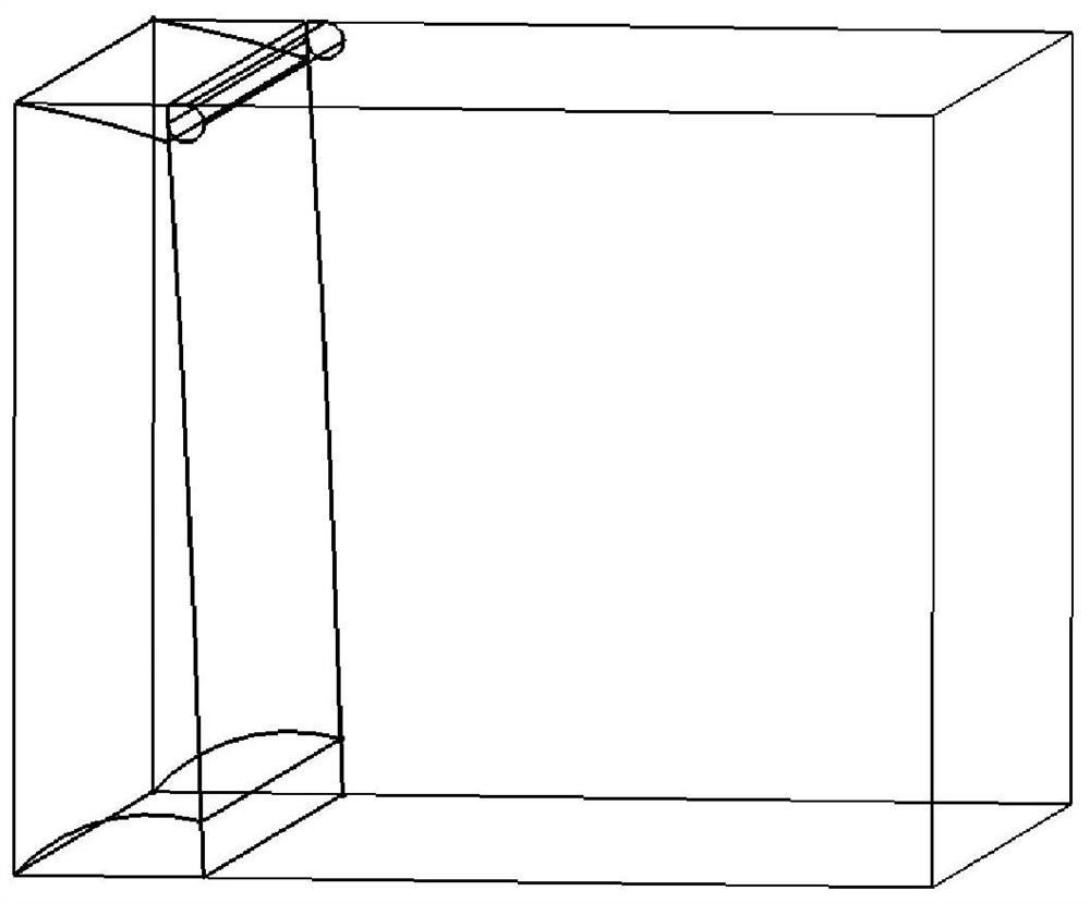
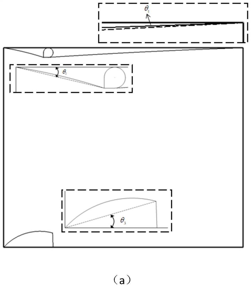
[0031] This embodiment proposes a new structure of a single-leaf valve. The valve plate is located on the upper part of the main body of the damper, the shaft is located on one side of the valve plate, and the upper and lower seals are located on the same side. When the damper is closed, the position of the valve plate is different from that of a conventional single-leaf valve. Specifically, the valve plate is located on the upper part of the damper body, the rotating shaft is located on the side of the valve plate, the first seal and the second seal are located on the fluid inlet side, when the valve plate rotates around the rotating shaft to the lower part of the damper body, the valve The plate is in contact with the second seal; and in the air valve proposed by the present invention, the first seal has a first curved surface, and the first curved surface is concave toward the fluid inlet side of the air valve; the second seal includes a second curved surface and an inclined ...


PUM


Abstract

The invention proposes a damper in a ventilation and air-conditioning system, which includes a damper body, a valve plate located on the upper part of the damper body, a rotating shaft for rotating the valve plate on one side of the valve plate, and a valve body connected to the damper body and the valve plate at the same time. The first seal on the side; also includes the second seal located at the lower part of the damper body, when the valve plate rotates around the rotation axis to the lower part of the damper body, the valve plate contacts with the second seal, both the first seal and the second seal are located at the lower part of the damper body fluid inlet side of the valve. The results show that, at the same caliber and at different wind speeds (3m / s-12m / s), the drag reduction degree of the air valve of the present invention is very obvious compared with the traditional single-leaf valve, and the local drag reduction rate ranges from 81.4% to 87.16%.

Description

technical field [0001] The invention belongs to the technical field of reducing resistance of local components of pipelines, and relates to resistance evaluation of local components of ventilation and air-conditioning pipelines, in particular to a damper structure in a ventilation and air-conditioning system. Background technique [0002] With the development of science and technology and economy, people's requirements for living standards are getting higher and higher. Therefore, ventilation and air conditioning systems have become an indispensable part of buildings, and their energy consumption has also increased significantly. The energy consumption of the ventilation and air conditioning system is one of the main energy consumption in buildings, accounting for about 65% of building energy consumption, and with the development of building intelligence, there is still a rising trend, in which the wind energy caused by resistance Energy consumption can account for 30% to 50...

Claims


Application Information

Patent Timeline
Patent Type & Authority Patents(China)
IPC IPC(8): F16K1/20F16K1/32F24F11/72
CPCF16K1/2042F16K1/32F24F11/72
Inventor 高然文诗豪张恒春来婷厉海萌吉铮李安桂
Owner XI'AN UNIVERSITY OF ARCHITECTURE AND TECHNOLOGY
Learn More