
Tunneling equipment and control method of tunneling equipment

A control method and equipment technology, applied in drilling equipment and methods, drilling automatic control systems, mining equipment, etc., can solve the problems of construction period and investment adverse effects, insufficient rotary drilling force, extended construction period, etc., to achieve Ensure structural controllability and stability, stable and reliable structural guarantee, and improve the effect of construction quality

Pending Publication Date: 2019-08-02
CHINA RAILWAY CONSTR HEAVY IND
View PDF0 Cites 2 Cited by
  • Summary
  • Abstract
  • Description
  • Claims
  • Application Information

AI Technical Summary

Problems solved by technology

[0002] In the current excavation of railway tunnels, about 30% to 40% of the geological structure belongs to weak surrounding rocks. Due to the lack of self-bearing capacity and rigidity of the weak surrounding rocks, the arch feet of the support will sink. Once the construction method is improper, it is easy to produce Engineering disasters such as deformation encroachment, support cracking, and partial collapse not only seriously affect construction safety and construction quality, but also adversely affect construction schedule and investment. Many tunnels, including the Xingwangmao Tunnel of the Taizhongyin Railway, etc., due to the poor self-stabilization ability of the surrounding rock, large deformation, and water softening, have led to design changes, extended construction periods, and increased investment
[0003] In related technologies, the use of mechanical equipment for drilling operations has the problems of insufficient rotary drilling force, unable to meet the requirements of tunnel arch foot reinforcement and unable to effectively suppress the deformation of the arch foot

Method used


Image

  • Tunneling equipment and control method of tunneling equipment
  • Tunneling equipment and control method of tunneling equipment
  • Tunneling equipment and control method of tunneling equipment

Examples


Embodiment Construction

[0060] In order to understand the above-mentioned purpose, features and advantages of the present invention more clearly, the present invention will be further described in detail below in conjunction with the accompanying drawings and specific embodiments. It should be noted that, in the case of no conflict, the embodiments of the present application and the features in the embodiments can be combined with each other.

[0061]In the following description, many specific details are set forth in order to fully understand the present invention. However, the present invention can also be implemented in other ways different from those described here. Therefore, the protection scope of the present invention is not limited by the specific details disclosed below. EXAMPLE LIMITATIONS.

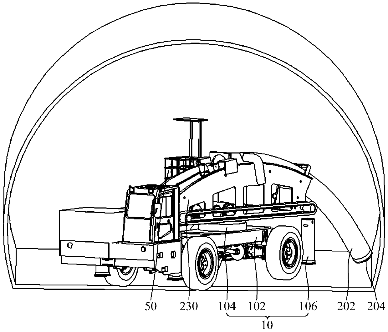
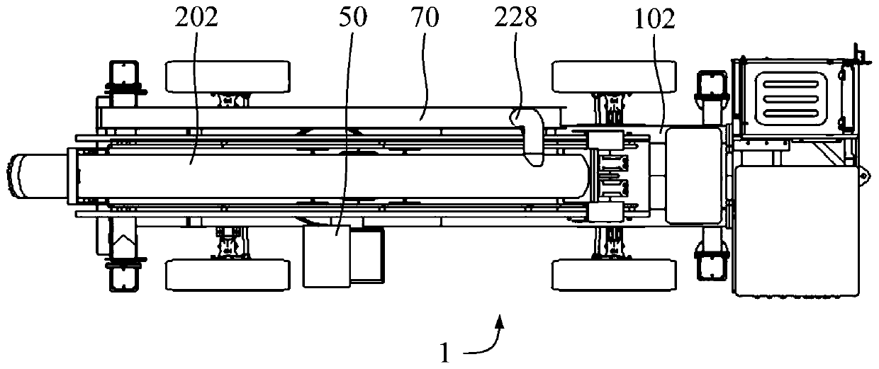
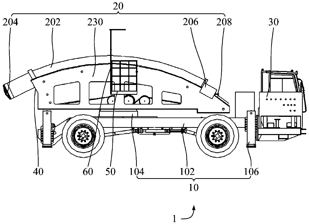
[0062] Refer below Figure 1 to Figure 11 The excavation equipment 1 and the control method of the excavation equipment 1 according to some embodiments of the present invention are described.

[006...


PUM


Abstract

The invention provides tunneling equipment and a control method of the tunneling equipment. The tunneling equipment comprises a walking assembly, a main machine and a controller. The main machine is arranged on the walking assembly, the main machine is provided with a guide rail, a curve-shaped guide part and a drill bit, the curve-shaped guide part is arranged on the guide rail, and the drill bitis connected with the curve-shaped guide part; the controller is connected with the walking assembly and the main machine, wherein the controller controls the drill bit to rotate and controls the curved guide part to move along the guide rail after controlling the walking assembly to move to a preset position. The structure of the tunneling equipment is reasonably arranged, the tunneling equipment tunnels and drills along the curve shape of the surrounding rock, therefore, the drilling depth can be increased in a targeted mode according to the specific actual use condition, so as to meet thehole forming depth requirement, the tunnel arch foot reinforcing requirement can be met, meanwhile, the structure provides a structure foundation for achieving fore-reinforcement and forepoling functions, and then the purposes of preventing arch feet from sinking and improving the surrounding rock stability can be achieved.

Description

technical field [0001] The invention relates to the technical field of excavation equipment, in particular to an excavation equipment and a control method for the excavation equipment. Background technique [0002] In the current excavation of railway tunnels, about 30% to 40% of the geological structure belongs to weak surrounding rocks. Due to the lack of self-bearing capacity and rigidity of the weak surrounding rocks, the arch feet of the support will sink. Once the construction method is improper, it is easy to produce Engineering disasters such as deformation encroachment, support cracking, and partial collapse not only seriously affect construction safety and construction quality, but also adversely affect construction schedule and investment. Many tunnels, including the Taizhongyin Railway Xingwangmao Tunnel, etc., due to the characteristics of poor self-stabilization, large deformation, and water softening of the surrounding rock, led to design changes, extended con...

Claims


Application Information

Patent Timeline
IPC IPC(8): E21B7/02E21D11/30E02D5/34E21B15/00E21B17/22E21B44/00
CPCE21B7/02E21B7/027E21D11/30E02D5/34E21B15/00E21B17/22E21B44/02
Inventor 刘飞香郑大桥廖金军李胜肖正航曹龙飞蒋海华伍容
Owner CHINA RAILWAY CONSTR HEAVY IND
Learn More