Gas mixing and supplying device in saw blade tempering furnace

A gas mixing and supplying device technology, applied in furnaces, heat treatment furnaces, furnace types, etc., can solve the problems of increasing unqualified rate, poor uniformity of temperature field, complicated process flow, etc., to reduce the generation of processing waste, eliminate the need for The effect of rising cost and overall compact structure

Pending Publication Date: 2019-08-02
东台艺新金属材料有限公司
View PDF1 Cites 0 Cited by
  • Summary
  • Abstract
  • Description
  • Claims
  • Application Information

AI Technical Summary

Problems solved by technology

Otherwise, there will be multiple tempering dead angles in the furnace cavity during tempering, and the uniformity of the temperature field will be poor, which will cause uneven heating of the workpiece, affect the tempering quality, increase the unqualified rate, and increase the cost; and most of the workpieces cannot be stacked. low utilization
[0003] Saw blades are usually tempered and need to be taken out of the tempering furnace for pickling and then surface phosphating to produce a bumpy surface for better adhesion of paint when subsequent painting. This process is complex and During the production process, a large amount of waste liquid that needs post-processing to avoid environmental pollution is generated, and the processing cost is high

Method used


Image

  • Gas mixing and supplying device in saw blade tempering furnace

Examples


Embodiment Construction

[0020] Specific embodiments of the present invention will be described in detail below in conjunction with the accompanying drawings.

[0021] Specific embodiments of the present invention will be described in detail below in conjunction with the accompanying drawings.

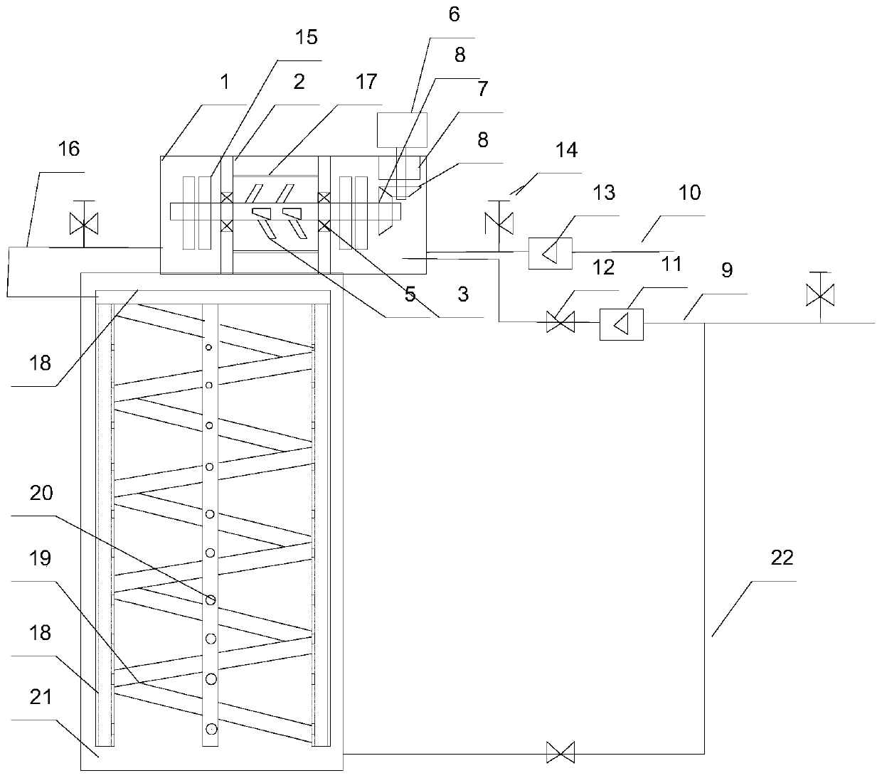
[0022] Such as figure 1 As shown, the gas mixing supply device in the saw blade tempering furnace includes a spiral gas supply pipe 18 arranged on the inner wall of the furnace body 21, and four gas pipes passing through the gas supply pipe 18 arranged on the inner wall of the furnace body 21 along the axial direction of the furnace body 21 Distributing pipe 19, gas outlet pipe 18 is provided with air outlet 20 on the part facing the furnace, and the aperture of said air outlet 20 increases gradually along the direction away from the inlet end; one end of gas distribution pipe 19 is closed, and the other end is connected with the ring The air intake pipe is connected;

[0023] It also includes an airtight cy...


PUM


Abstract

The invention discloses a gas mixing and supplying device in a tempering furnace. By means of the gas mixing and supplying device in the tempering furnace, gas in the tempering furnace can be evenly distributed, and convex points capable of easily adhering to a paint surface are easily generated on the surface of a tempered saw blade. The device comprises a spiral gas supply pipe arranged on the inner wall of a furnace body, and at least three gas distribution pipes which penetrate through the gas supply pipe and are arranged on the inner wall of the furnace body in the axial direction of thefurnace body. The device further comprises a closed cylinder arranged outside the furnace body. Two annular supports are oppositely arranged in the cylinder, bearing blocks are arranged on the annularsupports, a mixing shaft penetrates between the two bearing blocks, and a power device for driving the mixing shaft to rotate is arranged on the cylinder. A plurality of circulating holes allowing gas to pass are formed in the supports, and an oxygen inlet pipe and a nitrogen inlet pipe are arranged on one side of the cylinder. Two to four turbine blades are arranged at the two ends, outside thebearing blocks, on the mixing shaft respectively, a gas outlet pipe is arranged on the other side of the cylinder, the gas outlet pipe is connected with the gas supply pipe in the tempering furnace, and an air guide cylinder sleeves the mixing shaft and is arranged between the two supports.

Description

technical field [0001] The invention relates to a gas mixing and supplying device in a saw blade tempering furnace. Background technique [0002] In existing tempering furnaces, stirring shafts are often used to distribute the heated gas (usually nitrogen) in the furnace evenly, such as a tempering device described in patent ZL201720293559.7. Otherwise, there will be multiple tempering dead angles in the furnace cavity during tempering, and the uniformity of the temperature field will be poor, which will cause uneven heating of the workpiece, affect the tempering quality, increase the unqualified rate, and increase the cost; and most of the workpieces cannot be stacked. Low utilization. [0003] Saw blades are usually tempered and need to be taken out of the tempering furnace for pickling and then surface phosphating to produce a bumpy surface for better adhesion of paint when subsequent painting. This process is complex and During the production process, a large amount of...

Claims


Application Information

Patent Timeline
IPC IPC(8): C21D9/24C21D1/74
CPCC21D9/24C21D1/74
Inventor 钱建新
Owner 东台艺新金属材料有限公司
Why Eureka
Try Eureka