Automatic conveying and distributing system

A diversion system and conveyor belt technology, applied in the direction of conveyor objects, transportation and packaging, can solve the problems of affecting production quality, increasing the cost of automatic conveying diversion, reducing the total production volume, etc., to achieve the effect of increasing practicability

Active Publication Date: 2019-08-02
BAOTOU VOCATIONAL & TECHN COLLEGE
View PDF5 Cites 1 Cited by
  • Summary
  • Abstract
  • Description
  • Claims
  • Application Information

AI Technical Summary

Problems solved by technology

[0002] In modern factory production, manual transportation is often used for the classification of some goods. The process is extremely time-consuming and labor-intensive. Not only the accuracy and frequency of transportation are quite large, which directly affects the production quality, but also the handling process may cause danger and aggravate A certain dust effect in the workshop, coupled with the low efficiency of the overall feeding of the workshop, leads to a reduction in the total production volume and a long production time, so an automatic conveying and diverting system is often used, and the existing automatic conveying and diverting system In the process, the sliding board is generally used to further transport the items conveyed by the shunt, and in the process of conveying the objects, there will always be various batches of objects with different sizes and volumes. In the process, it is always necessary to replace different conveying slides in order to facilitate the normal operation of the packaging conveying work. At that time, this practice increased the cost of automatic conveying and diversion to a certain extent, and made the existing automatic conveying and diversion system in the process of operation. has certain limitations

Method used


Image

  • Automatic conveying and distributing system
  • Automatic conveying and distributing system
  • Automatic conveying and distributing system

Examples


Embodiment 1

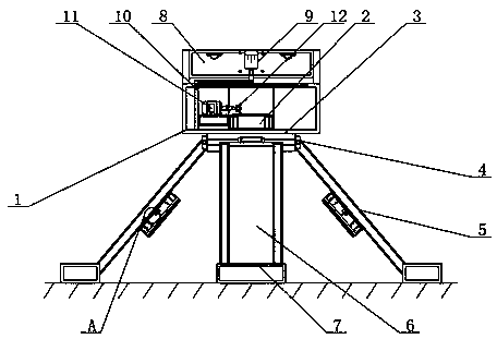
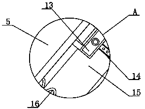
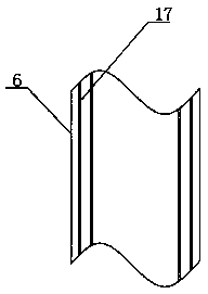
[0021] see Figure 1-5 , the present invention provides the following technical solutions: an automatic conveying and diverting system, including an outer shell 1 and a conveyor belt 2 placed inside the outer shell 1, a connecting block 3 welded on the lower surface of the outer shell 1, and a clamping block 4 arranged inside the connecting block 3 , a slide plate 6 is provided below the outer shell 1, the slide plate 6 is slidably connected to the connecting block 3 through the clamp block 4, grooves 17 are opened on both sides of the slide plate 6, and the side plates 5 are snapped and connected in the groove 17, One side of the side plate 5 is integrally formed with a pull plate 13, and a limit plate 15 is welded on the lower surface of the side plate 5 close to the position of the pull plate 13, and a limit groove 14 is opened at the middle position on the surface of the limit plate 15, and the outer shell 1 is provided with a connection plate 8, the connection plate 8 and...


PUM


Abstract

The invention belongs to the technical field of automatic conveying, and particularly relates to an automatic conveying and distributing system. The automatic conveying and distributing system comprises a shell and a conveyor belt placed in the shell, wherein a connecting block is welded to the lower surface of the shell, and a clamping block is arranged in the connecting block. According to the automatic conveying and distributing system, articles are conveyed into the shell through the conveyor belt in the using process, a pushing block at the output end of an air pump can be used for pushing the articles into different sliding plates for transmission, and when larger batches of articles are required to be conveyed and separated, rotary knobs on the front sides of pull plates can be separated from the pull plates, and the pull plates are pulled downwards, so that side plates in grooves are pulled to a certain distance; and the knobs are screwed into round holes in limiting grooves, the two sliding plates are rotated, and the two sliding plates are spliced together to form a larger conveying plate, so that the problem that the existing automatic conveying and distributing system needs to be replaced when the large articles are encountered is solved.

Description

technical field [0001] The invention belongs to the technical field of automatic transportation, and in particular relates to an automatic transportation and distribution system. Background technique [0002] In modern factory production, manual transportation is often used for the classification of some goods. The process is extremely time-consuming and labor-intensive. Not only the accuracy and frequency of transportation are quite large, which directly affects the production quality, but also the handling process may cause danger and aggravate A certain dust effect in the workshop, coupled with the low efficiency of the overall feeding of the workshop, leads to a reduction in the total production volume and a long production time, so an automatic conveying and diverting system is often used, and the existing automatic conveying and diverting system In the process, the sliding board is generally used to further transport the items conveyed by the shunt, and in the process ...

Claims


Application Information

Patent Timeline
Patent Type & Authority Applications(China)
IPC IPC(8): B65G47/44
CPCB65G47/44
Inventor 王德志王政李瑜
Owner BAOTOU VOCATIONAL & TECHN COLLEGE
Why Eureka
Try Eureka