Permanent-magnet industrial large fan

An industrial and fan technology, applied in the field of permanent magnet industrial large fans, can solve the problems of potential safety hazards, inconvenient installation, and high cost of use, and achieve the effect of solving the problem of stable use, no potential safety hazards, and reduced failure rate.

Inactive Publication Date: 2019-07-26
宁波英利腾机械有限公司
View PDF4 Cites 0 Cited by
  • Summary
  • Abstract
  • Description
  • Claims
  • Application Information

AI Technical Summary

Problems solved by technology

[0004] The core structure of the existing large industrial fan is a geared motor. Because of the complex structure and high requirements for gear machining accuracy, problems such as oil leakage, loud noise, and vibration of the reducer often occur during use. At the same time, because of the structure of the gear box, Regular high-altitude operations are required to replace gear oil, resulting in high operating costs
Moreover, because the length of the deceleration motor is long, the height of the industrial large fan host itself is high, and it cannot be installed in many workshop environments, especially in environments with driving.
At the same time, the height of the host is high and the size is large. It does not look light and beautiful when installed in the workshop environment.
At the same time, the existing permanent magnet industrial large fans have insufficient safety protection measures, which may cause potential safety hazards

Method used


Image

  • Permanent-magnet industrial large fan
  • Permanent-magnet industrial large fan

Examples


Embodiment Construction

[0018] The specific implementation manner of the present invention will be further described below in conjunction with the accompanying drawings. Wherein the same components are denoted by the same reference numerals.

[0019] It should be noted that the words "front", "rear", "left", "right", "upper" and "lower" used in the following description refer to the directions in the drawings, and the words "inner" and "outer ” refer to directions towards or away from the geometric center of a particular part, respectively.

[0020] In order to make the content of the present invention more clearly understood, the technical solutions in the embodiments of the present invention will be clearly and completely described below in conjunction with the drawings in the embodiments of the present invention.

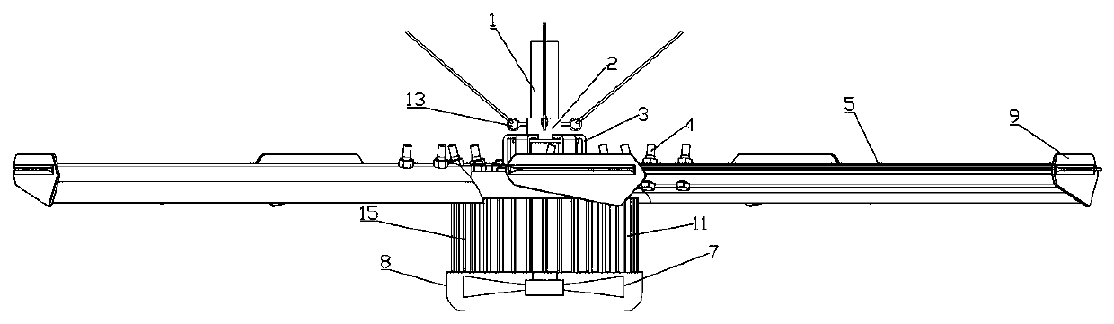
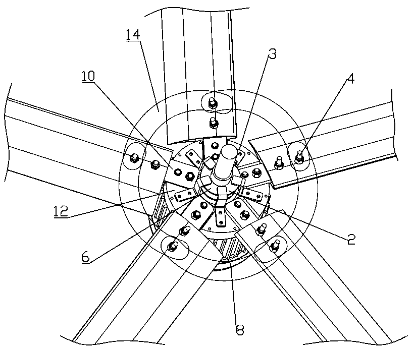
[0021] Such as figure 1 , 2 As shown, a large permanent magnet industrial fan includes: a permanent magnet motor, the permanent magnet motor is placed inside the motor casing 11, a m...


PUM


Abstract

The invention discloses a permanent-magnet industrial large fan. The permanent-magnet industrial large fan comprises a permanent-magnet motor, wherein the permanent-magnet motor is arranged at an inner side of a motor shell, a motor shaft is arranged on the permanent-magnet motor, a safety fuse ring sleeves an outer side of the motor shaft, a round ring sleeves a part below the safety fuse ring and the outer side of the motor shaft, a fuse hook is arranged on the round ring, a fan fixed bottom disc sleeves a part below the round ring and the outer side of the motor shaft, blades are in bolt connection with the fan fixed bottom disc by a plugin, the blades are connected with a fastening bolt by a fuse sheet, a tail wing is arranged at the other end of each blade, a motor tail cover is arranged at a bottom end of the motor shell, and a small-size fan for cooling is arranged at an inner side of the motor tail cover. By the permanent-magnet industrial large fan, the large-size permanent-magnet industrial fan can very stably run, meanwhile, a safety protection measure is added, and the permanent-magnet industrial large fan is more stable and safer to run.

Description

technical field [0001] The invention relates to the field of fan equipment, in particular to a large permanent magnet industrial fan. Background technique [0002] In summer, the factory environment is stuffy and the air is not circulated, which greatly affects the work efficiency of employees. Especially in the workshops of many labor-intensive industries, the personnel are concentrated, and the problem of ventilation and cooling is urgently needed. Central air-conditioning is used for refrigeration, the installation cost is high, the energy consumption remains high, and the later maintenance cost is also very high. The use of ordinary floor fans to cool down not only affects the arrangement of equipment in the workshop, but also makes people move around, which is unsightly and untidy. Fans are scattered everywhere, and wires run randomly, which can easily cause electric leakage accidents and even fire hazards. At the same time, because a large number of fans are needed to ...

Claims


Application Information

Patent Timeline
IPC IPC(8): H02K7/14H02K5/18H02K9/06F04D25/08F04D29/58
CPCF04D25/082F04D25/088F04D29/5806H02K5/18H02K7/14H02K9/06
Inventor 舒皓望
Owner 宁波英利腾机械有限公司
Why Eureka
Try Eureka