
Battery cooling plate with integrated air vents

A technology of cooling plate and exhaust port, which is applied in the direction of battery, secondary battery, exhaust plug device, etc., can solve the problem that the cooling plate does not include exhaust port, etc.

Inactive Publication Date: 2019-07-26
HANON SYST
View PDF5 Cites 50 Cited by
  • Summary
  • Abstract
  • Description
  • Claims
  • Application Information

AI Technical Summary

Problems solved by technology

Disadvantageously, the cooling plates known in the prior art do not include vents to properly vent gases from the battery cells

Method used


Image

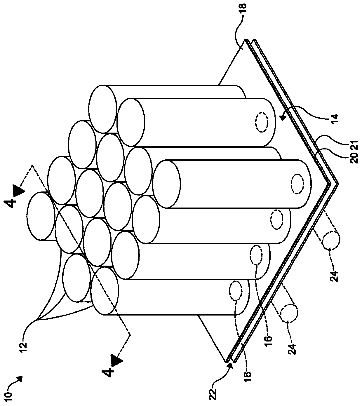
  • Battery cooling plate with integrated air vents
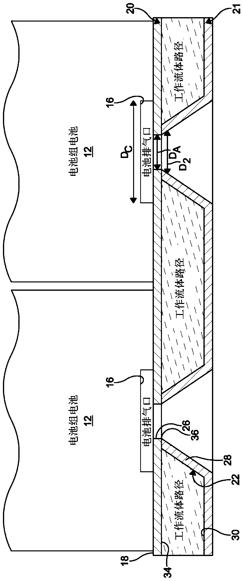
  • Battery cooling plate with integrated air vents
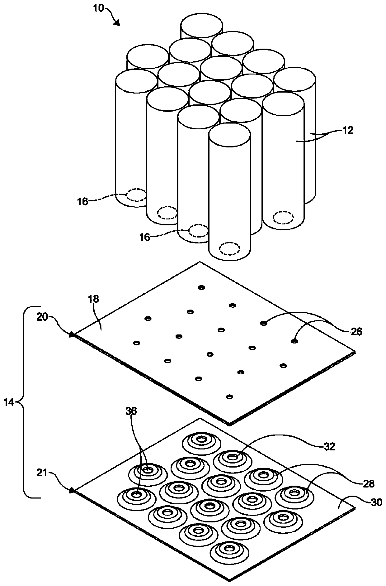
  • Battery cooling plate with integrated air vents

Examples


Embodiment Construction

[0014] The following detailed description and accompanying drawings describe and illustrate various embodiments of the invention. The description and drawings are intended to enable a person skilled in the art to make and use the invention and are not intended to limit the scope of the invention in any way. With respect to the methods disclosed, the steps presented are exemplary in nature and, therefore, the order of the steps is not necessary or critical. As used herein, this will be clearly understood by those skilled in the art based on the specification as well as the accompanying drawings.

[0015] The term electric vehicle as used herein is defined to include vehicles that use electric power as all or part of the driving force of the vehicle. Electric vehicles may include hybrid electric vehicles, plug-in electric vehicles, all-electric or battery pack electric vehicles, plug-in hybrid vehicles, fuel cell electric vehicles, or other currently known or later developed ve...


PUM


Abstract

A cooling system for cooling battery cells includes a plate assembly defining a chamber. The chamber is configured to receive a fluid therein. A plurality of apertures extend through the plate assembly. Each of the plurality of apertures is configured to align with a cell vent of one of the battery cells.

Description

technical field [0001] The invention relates to a cooling system for a battery module comprising a cooling plate with integrated air vents. Background technique [0002] It is well known that batteries are used in vehicles that use electricity for at least a portion of their propulsion. Vehicles using battery cells are, for example, electric vehicles, hybrid electric vehicles, plug-in electric vehicles, battery-pack electric vehicles, fuel cell electric vehicles, and plug-in hybrid vehicles. [0003] Battery cells typically utilize lithium-ion chemistry and are typically packed into cylindrical or prismatic housings to form battery modules. When charging and discharging the battery cells, the current flowing through the battery cells generates heat. Additionally, exothermic chemical reactions and ambient temperatures can add heat to the battery through conduction, convection, and / or radiation. The added heat increases the temperature of the battery cells, negatively impac...

Claims


Application Information

Patent Timeline
Patent Type & Authority Applications(China)
IPC IPC(8): H01M10/6556H01M10/6554H01M10/6567H01M10/643H01M10/625H01M10/613
CPCH01M2220/20H01M10/613H01M10/625H01M10/643H01M10/6554H01M10/6556H01M10/6567H01M10/647H01M50/30Y02E60/10Y02T10/70B60Y2200/91B60Y2200/92B60L58/26H01M10/6563H01M10/6566
Inventor 詹姆斯·塔西奥普洛斯卡斯特里奥特·沙斯卡库尔特·普特博
Owner HANON SYST
Learn More