
Central slip-limiting differential device, driving system comprising same, and application

A differential device, central technology, applied in the direction of control device, transportation and packaging, vehicle components, etc., can solve the problems of increased fuel cost, increased vehicle cost, increased vehicle weight, etc., and achieves the effect of short response time

Active Publication Date: 2019-07-26
青岛鲜佰客食品科技有限公司
View PDF21 Cites 3 Cited by
  • Summary
  • Abstract
  • Description
  • Claims
  • Application Information

AI Technical Summary

Problems solved by technology

But full-time four-wheel drive has a differential device, so it will not only increase the weight of the vehicle, but more importantly, increase the vehicle cost of the vehicle, and the fuel cost will also increase

Method used


Image

  • Central slip-limiting differential device, driving system comprising same, and application
  • Central slip-limiting differential device, driving system comprising same, and application

Examples


Embodiment 1

[0036] Such as figure 1 As shown, a central limited-slip differential device includes a power input shaft 101, a clutch 2, an intermediate transmission device 102, a ratchet assembly 1 and a power output shaft 103, wherein,

[0037] The clutch 2 includes a detachable and engaging active part and a driven part. The clutch 2 can be a multi-clutch plate type, or a jaw type, or a known other type of clutch 2. The combination of the clutch 2 The control mode of disconnection and disconnection can be controlled by the controller, and the active part is installed on the power input shaft 101, so as to be connected with the power mechanism and drive the active part to rotate; the power mechanism can be a power source (such as a motor, a drive Cylinder or engine 10 etc.) and the combined structure of transmission mechanism.

[0038]The ratchet assembly 1 includes parts A and B that cooperate with each other, and the driven part of the clutch 2 is connected with the part A of the ratch...

Embodiment 2

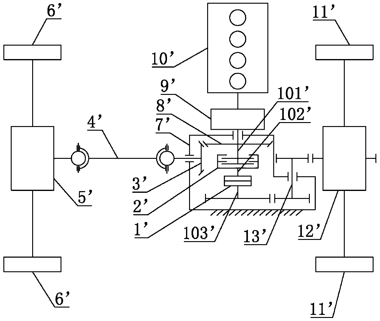
[0057] The central limited-slip differential device in Embodiment 2 is the same as Embodiment 1, which includes a power input shaft 101', a clutch 2', an intermediate transmission device 102', a ratchet assembly 1' and a power output shaft 103'. For specific structures, refer to Example 1.

[0058] But the drive system of its four-wheeled vehicle is slightly different from Embodiment 1, and its drive system comprises a kind of central limited-slip differential device described above, also comprises power mechanism, rear wheel drive shaft 4 ', rear axle differential 5 ', two rear wheels 6', front wheel drive shaft 13', front axle differential 12' and two front wheels 11', wherein,

[0059] The power mechanism includes an engine 10', a gearbox 9' and a central transfer case 7', the longitudinal direction of the engine 10' is consistent with the transverse direction of the four-wheeled vehicle, and the central transfer case 7' has driving bevel gears meshing with each other 8' a...


PUM


Abstract

The invention discloses a central slip-limiting differential device, which comprises a power input shaft, a clutch, an intermediate transmission device, a ratchet assembly and a power output shaft. The clutch comprises a driving part and a driven part capable of being detached and engaged, and the power input shaft is provided with the driving part to be connected with a power mechanism and drivethe driving part to rotate; the ratchet assembly comprises a part A and a part B which are matched with each other, and the driven part of the clutch is connected with the part A of the ratchet assembly through the intermediate transmission device; the part B of the ratchet assembly is mounted on the power output shaft, and the rotating speed of the part B is not smaller than the rotating speed ofthe part A; and a ratchet or a pawl is adopted as the part A, and a pawl or a ratchet matched with the part A is adopted as the part B. Through cooperation of the clutch and the ratchet assembly, thepart A and the part B can rotate synchronously or asynchronously, different using occasions are met, and thus a four-wheel automobile can be switched to adopt a two-wheel drive mode or a four-wheel drive mode.

Description

technical field [0001] The invention belongs to the field of four-wheel drive vehicles, and more specifically relates to a central limited-slip differential device, a driving system including the same and an application thereof. Background technique [0002] The driving form of the car is divided into front-wheel drive, rear-wheel drive and four-wheel drive. Usually, in order to enhance the handling and passability of the car, four-wheel drive will be preferred. For four-wheel drive, in short, it is to transmit the power of the engine to the four wheels, there is a mechanical transmission, and there is also a dual-motor coupling transmission (the front axle and the rear axle each have a motor). Overall four-wheel drive is divided into three categories: part-time four-wheel drive, timely four-wheel drive and full-time four-wheel drive. [0003] The central transfer case of part-time four-wheel drive and timely four-wheel drive has no differential device, and can only switch ...

Claims


Application Information

Patent Timeline
Patent Type & Authority Applications(China)
IPC IPC(8): B60K17/344B60K17/02B60K17/16
CPCB60K17/02B60K17/165B60K17/344
Inventor 韩祥震韩晴晴孟佳齐许坤
Owner 青岛鲜佰客食品科技有限公司
Learn More