Ceiling lamp with internal magnetic rotary screws

A ceiling lamp and screw technology, which is applied to the parts of lighting devices, lighting devices, fixed lighting devices, etc., can solve the deformation of the cross groove and the flat groove, the screw cannot be rotated, and the screw cannot be screwed out from the object, etc. problem, to achieve the effect of being less susceptible to damage

Inactive Publication Date: 2019-04-19
王勇
View PDF0 Cites 2 Cited by
  • Summary
  • Abstract
  • Description
  • Claims
  • Application Information

AI Technical Summary

Problems solved by technology

[0002] In the prior art, the connection between the ceiling lamp and the wall is mostly a threaded connection. The traditional threaded connection mostly uses cross screws or slotted screws to thread the ceiling lamp and the wall, regardless of whether it is a cross screw or a flat screw. For slotted screws, the place where the screwdriver bit is inserted and rotated is always exposed to the outside. After a long time, the screws are prone to rust, and the rusted screws can be easily inserted into the cross groove or the flat groove for the screwdriver. Deformation causes the screw to fail to rotate, or in people's daily life, it often happens that the screw's cross groove or flat groove is deformed due to the excessive force of the screwdriver knob, so that the screw cannot be unscrewed from the object

Method used


Image

  • Ceiling lamp with internal magnetic rotary screws
  • Ceiling lamp with internal magnetic rotary screws

Examples


Embodiment 1

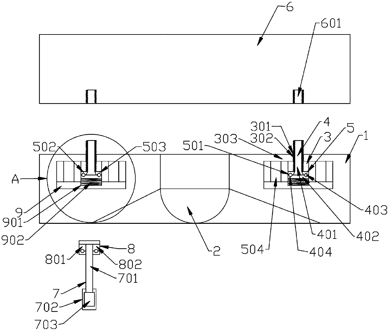
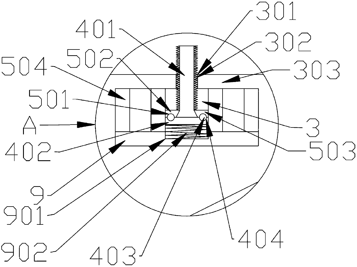
[0020] Example 1: see figure 2 , the applicant first drills a hole on the wall with an electric drill, and then places an expansion bolt in the hole, turns the screw protruding from the upper end of the ceiling lamp to place the hole with the expansion bolt, and the user only needs to hold the driver mechanism, so that the upper end surface of the driving mechanism and the lower end surface of the ceiling lamp are offset, and the two magnets with opposite magnetism attract each other, so at this time, the third magnetic block of the second magnetic mechanism will attract the first magnetic block of the first magnetic mechanism. The fourth magnetic block of the second magnetic mechanism can be attracted with the second magnetic block of the first magnetic mechanism; at this moment, the motor in the drive mechanism is turned on to make the motor run, and now the motor will drive the motor at the upper end of the connecting rod through the connecting rod. The second magnetic mec...


PUM


Abstract

The invention discloses a ceiling lamp with internal magnetic rotary screws. The ceiling lamp comprises a lamp base and a lamp. The lamp is arranged on the lower end surface of the lamp base, a plurality of first cavities are arranged on the upper end surface of the lamp base, a fixing cavity is arranged in each first cavity, the lamp base can be detachably connected onto a wall by the fixing mechanisms, a first through hole is formed in the upper end surface of each first cavity, the upper ends of the fixing mechanisms can penetrate the upper end surface of the lamp base via the first throughholes and can be fixedly connected with the wall by the first through holes, each fixing mechanism comprises a screw, threaded grooves which can be connected with the outer side walls of the screws in a threaded manner are peripherally formed in the inner side walls of the first through holes, first magnetic mechanisms are arranged at the lower ends of the screws, a driving mechanism is further arranged below the lamp base, the fixing mechanisms in the lamp base can be driven to rotate by the driving mechanism by the aid of users, the lamp base can be connected with threaded holes of the wallin a threaded manner by the driving mechanism, the driving mechanism comprises a connecting rod and a grabbing portion, the grabbing portion is arranged at the lower end of the connecting rod, a second magnetic mechanism which can be magnetically connected with the first magnetic mechanisms is arranged at the upper end of the connecting rod, a motor is arranged in the grabbing portion, and the second magnetic mechanism can be driven to peripherally rotate by the motor via the connecting rod.

Description

technical field [0001] The invention relates to the technical field of ceiling lamps, in particular to a ceiling lamp containing magnetic rotating screws. Background technique [0002] In the prior art, the connection between the ceiling lamp and the wall is mostly a threaded connection. The traditional threaded connection mostly uses cross screws or slotted screws to thread the ceiling lamp and the wall, regardless of whether it is a cross screw or a flat screw. For slotted screws, the place where the screwdriver bit is inserted and rotated is always exposed to the outside. After a long time, the screws are prone to rust, and the rusted screws can be easily inserted into the cross groove or the flat groove for the screwdriver. Deformation occurs so that the screw cannot be rotated out, or in people's daily life, it often occurs that the cross groove or the flat groove of the screw is deformed by the user because the screwdriver knob is too hard, so that the screw cannot be ...

Claims


Application Information

Patent Timeline
IPC IPC(8): F21S8/04F21V21/00F21V21/03B25B21/00
CPCF21S8/04B25B21/002F21V21/00F21V21/03
Inventor 王勇
Owner 王勇
Why Eureka
Try Eureka