
Tail-tin-plated type plug power line detecting equipment

A technology for testing equipment and power cords, which is applied in the field of testing equipment for tail tinned plug power cords, can solve problems such as low production efficiency, inability to straighten the entire line, and irregular incoming materials, so as to save production costs and improve production. Efficiency and yield rate, the effect of reducing workload

Inactive Publication Date: 2019-07-23
BULL GRP CO LTD
View PDF9 Cites 3 Cited by
  • Summary
  • Abstract
  • Description
  • Claims
  • Application Information

AI Technical Summary

Problems solved by technology

[0003] However, the distribution of internal and external high-voltage manual operations is safe, and the polarity continuity test is currently performed in a fixed sequence. The extended power cord is a three-core wire, fire, zero, and ground wires. When testing polarity continuity, it must be tested in sequence, and it is easy for employees to operate. Misjudgment
At the same time, the injection molding of the head and tail of the power cord and the tinning process of the tail, the length and straightness of the core wire at the end of the power cord are uncontrollable, and the incoming material is irregular (bent), and the operation of straightening the whole line by itself cannot be performed with existing equipment; Continuity is now detected in order, and the polarity of the core wire at the end of the power cord is manually tested by identifying the color. During the test process, the equipment often causes an alarm due to a wrong sequence, resulting in low production efficiency and a high error rate.

Method used


Image

  • Tail-tin-plated type plug power line detecting equipment
  • Tail-tin-plated type plug power line detecting equipment
  • Tail-tin-plated type plug power line detecting equipment

Examples


Embodiment Construction

[0034] In order to make it easy to understand the technical means, creative features, goals and effects achieved by the present invention, the following examples are combined with the appended Figures 1 to 5 The detection equipment for the tail tinned plug power cord provided by the present invention will be described in detail.

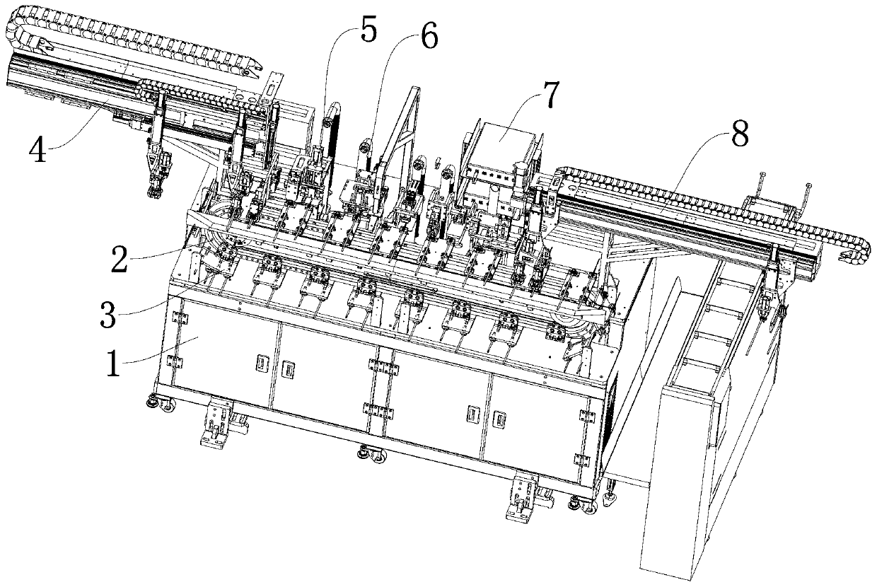
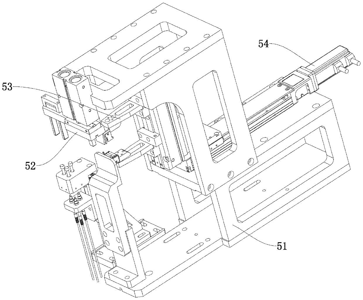
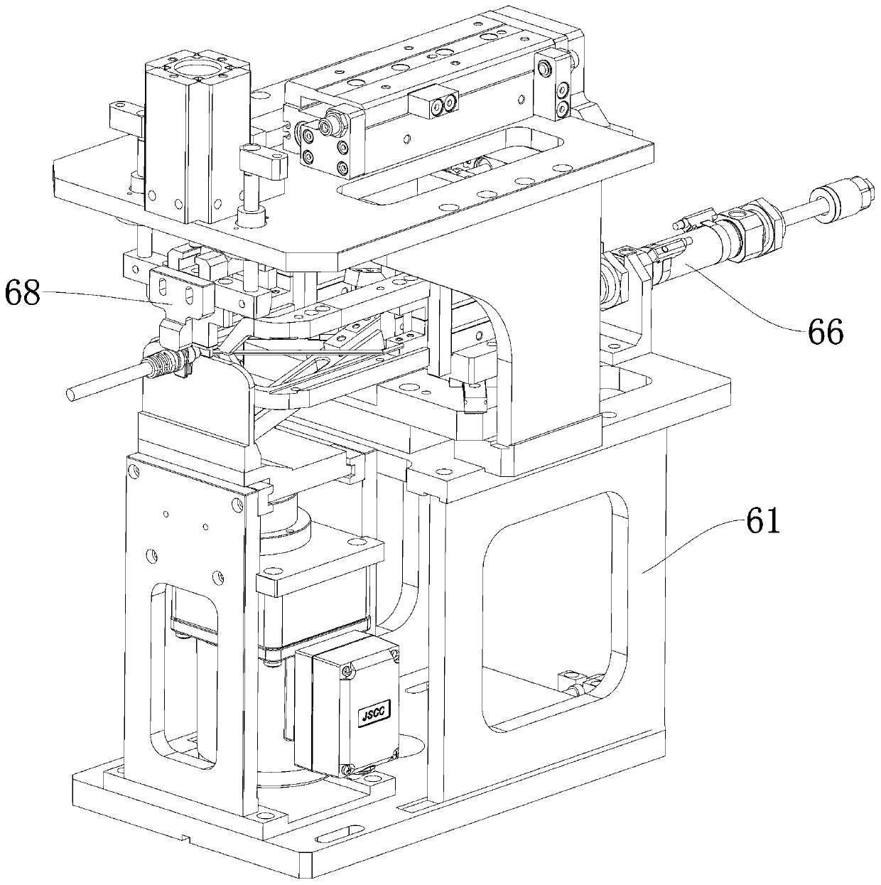
[0035] refer to Figures 1 to 5 The tail tinned plug power cord detection equipment provided by the present invention includes a frame 1, on which a circular conveying line 2 is arranged, and at least one jig 3 for arranging the plug wire is installed on the circular conveying line 2 ; along the conveying direction of the circular conveying line 2, a feeding mechanism 4 for transferring the plug wires from the previous process to the carrier, and a three-phase wire for exposing the tail ends of the plug wires are sequentially arranged on the frame 1 Tail shaping mechanism for shaping operation 5, tail branching mechanism for splitting the three-pha...


PUM


Abstract

The invention discloses tail-tin-plated type plug power line detecting equipment, which comprises a rack. A circular conveying line is arranged on the rack; one or more jigs are mounted on the circular conveying line; a feeding mechanism, a tail shaping mechanism, a tail branching mechanism, a high-voltage tester and a discharging mechanism are sequentially arranged on the rack in the conveying direction of the circular conveying line; and a CCD device is further arranged on the high-voltage tester and used for recognizing the position where a triple-phase line is located after branching operation, and inner high-voltage, outer high-voltage, polarity and on-off detection is conducted correspondingly by the high-voltage tester. According to the tail-tin-plated type plug power line detectingequipment, carrying, shaping, branching and detecting operation of plug lines after injection molding can be completed automatically, bent and irregular tail core lines can be shaped and straightened, manual assisting is not needed, the working burden of an operator is greatly reduced, the production efficiency is greatly improved, the yield is greatly increased, and the production cost is saved.

Description

technical field [0001] The invention relates to the technical field of plug cord detection equipment, in particular to a tail tinned plug power cord detection equipment. Background technique [0002] For some national standard household power cords, the tail wire process needs to be tinned, and the power cord must be tested for internal and external high voltage, polarity, and continuity in accordance with national standards. At present, the conventionally used high-voltage comprehensive tester generally needs to manually insert the plug into the fixture to complete the internal and external high voltage and polarity continuity test. [0003] However, the distribution of internal and external high-voltage manual operations is safe, and the polarity continuity test is currently performed in a fixed sequence. The extended power cord is a three-core wire, fire, zero, and ground wires. When testing polarity continuity, it must be tested in sequence, and it is easy for employees ...

Claims


Application Information

Patent Timeline
IPC IPC(8): G01R31/00G01R31/02
CPCG01R31/00G01R31/59G01R31/50
Inventor 李辉强张应龙王清旺余佳明
Owner BULL GRP CO LTD
Learn More