Pitot tube device for measuring pressure pulsation of hypersonic wind tunnel

A wind tunnel pressure and hypersonic technology, applied in the field of fluid mechanics, to achieve the effect of solving large errors, improving accuracy, and weakening reflection oscillations

Active Publication Date: 2019-07-23
HUAZHONG UNIV OF SCI & TECH
View PDF5 Cites 2 Cited by
  • Summary
  • Abstract
  • Description
  • Claims
  • Application Information

AI Technical Summary

Problems solved by technology

[0004] Aiming at the above defects or improvement needs of the prior art, the present invention provides a pitot tube device for pressure pulsation measurement in a hypersonic wind tunnel, thus solving the problem when the existing pitot tube is used to measure pressure pulsation in a hypersonic wind tunnel. Technical problems with large errors

Method used


Image

  • Pitot tube device for measuring pressure pulsation of hypersonic wind tunnel
  • Pitot tube device for measuring pressure pulsation of hypersonic wind tunnel
  • Pitot tube device for measuring pressure pulsation of hypersonic wind tunnel

Examples


Embodiment 1

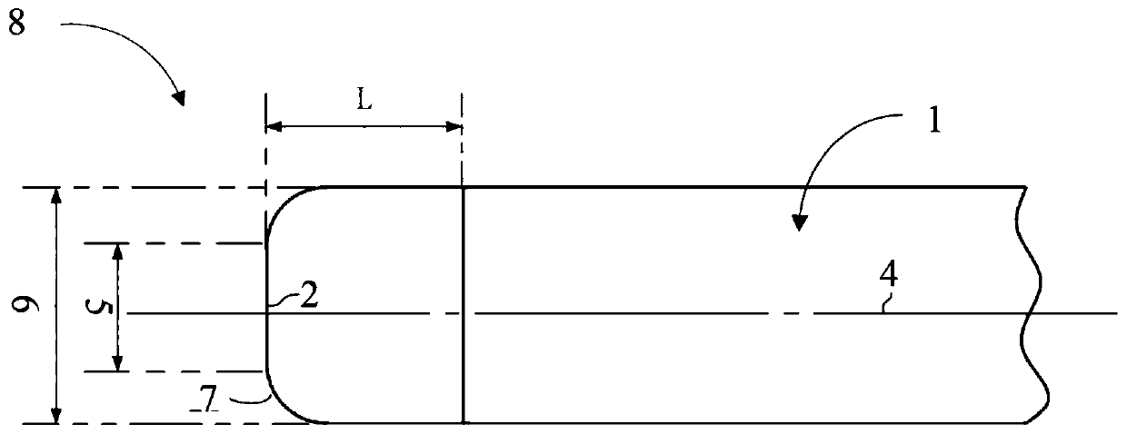
[0029] figure 1 The structural diagram of Example 1 is shown in . The pitot tube device 8 includes a cylindrical body 1 and a sensor 2, and an internally supported connecting piece 3 with the central axis 4 of the cylindrical body and the sensor as the center of rotation. exist figure 1 In Embodiment 1, the cylindrical body includes a front end plane 5, a cylindrical shoulder 6 and a transition fillet 7 therebetween. In this case, the transition radius 7 may be removed or replaced by another aerodynamically suitable contour. Considering the machining problem in Embodiment 1, the main body of the cylindrical shape is divided into two sections at a distance from the front end plane L along the central axis. The length L is affected by the axial length of the sensor and the design of the internally supported connector.

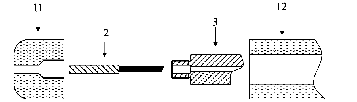
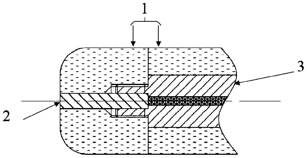
[0030] figure 2 The exploded cross-sectional view of the Pitot tube device is shown. The Pitot tube can alleviate the disturbance reflection problem of the...

Embodiment 2

[0036] Figure 4 Demonstrates different ways to attenuate a pitot tube for ultrasonic measurement of disturbance reflections. In the second embodiment, the pitot tube device is directly composed of the main body 1 and the sensor 2 . The main body 1 formed of a porous metal material can reduce the reflection of disturbances in the supersonic flow field. The positioning connection between the main body 1 and the sensor 2 is completed by the hollow cavity of the main body 1 . The outer profile of the body 1 can be modified to suit the aerodynamic shape. The sensor 2 can be selected from sensors of different models and types.

[0037] Using porous metal materials for pitot tubes to measure pressure fluctuations in hypersonic incoming flow can eliminate part of the influence of incoming flow disturbances. The technical problem is that porous metal materials with different properties, such as permeability, porosity, etc., have great impact on experimental measurements. The corre...


PUM


Abstract

The invention discloses a pitot tube device for measuring pressure pulsation of a hypersonic wind tunnel, belonging to the field of fluid mechanics. The pitot tube device comprises a main body and a sensor, wherein the sensor is positioned in the hollow inner cavity of the main body, the main body is made of a porous metal material; the porous material is provided with micropore gaps, and can partially absorb disturbance waves such as sound waves, vortex waves and entropy waves without damaging a flow field structure. When the pitot tube device is used for measuring the pressure pulsation of the hypersonic wind tunnel, the main body made of the porous metal material absorbs the flow field disturbance and weakens the reflection oscillation of the flow field disturbance between a shock surface and the front end surface of the pitot tube device, and further improves the accuracy of the hypersonic wind tunnel pressure pulsation measurement. Therefore, the technical problem that when the pitot tube in the prior art is used for measuring the pressure pulsation of the hypersonic wind tunnel, a relatively large error exists is solved.

Description

technical field [0001] The invention belongs to the field of fluid mechanics, and more particularly relates to a pitot tube device for measuring pressure fluctuations in a hypersonic wind tunnel. Background technique [0002] At present, the main ground experimental research platform for hypersonic aerodynamics research is the hypersonic wind tunnel. After the construction of a conventional hypersonic wind tunnel is completed, the static and dynamic qualities of its flow field must be identified, where the dynamic quality refers to the modal characteristics of the free flow disturbance. At present, the quantitative calibration of the disturbance mode characteristics usually uses three quantities in the free flow of the wind tunnel: the pressure fluctuation, the density fluctuation, the total temperature fluctuation, the static temperature fluctuation and the speed fluctuation. The pressure pulsation in which is currently commonly used to measure the Pitot tube. Pitot tube ...

Claims


Application Information

Patent Timeline
Patent Type & Authority Applications(China)
IPC IPC(8): G01M9/04G01M9/06
CPCG01M9/04G01M9/06
Inventor 吴杰余涛赵家权
Owner HUAZHONG UNIV OF SCI & TECH
Why Eureka
Try Eureka