Cylinder block structure of hybrid opposed-piston and mixed-layer rotor-stator engine

A technology of opposing pistons and engines, applied in the direction of internal combustion piston engines, combustion engines, machines/engines, etc., can solve the problems of high center of gravity of the engine, large engine volume, too long cylinder, etc., and achieve the solution of installation position and installation space. Conflict, easy maintenance, light weight effect

Active Publication Date: 2021-02-23
辽宁方联发动机有限公司
View PDF9 Cites 0 Cited by
  • Summary
  • Abstract
  • Description
  • Claims
  • Application Information

AI Technical Summary

Problems solved by technology

In order to further meet the requirements of energy saving, emission reduction and green environmental protection, in recent years, the development and application of new energy technologies for environmentally friendly fuels have been explored. Among them, the rotor of the mixed-layer rotor stator electromagnetic engine is driven by a multi-layer lever, and the piston of the fuel electromagnetic double-sided hybrid piston engine has one side. The double-sided driving force of the fuel drive and the electromagnetic drive on the other side and the unique structure of the electromagnetic piston engine with the electromagnetic piston and permanent magnet have strong explosive power and good power consumption efficiency, which has become another exploration direction for the research and development of new energy engines, especially hybrid engines. Two pistons are placed in each cylinder of the opposed-piston coupling engine, which causes the cylinder to be too long and the engine to be too large. Using the central shaft as the main drive shaft causes the center of gravity of the engine to be placed too high, which is different from the existing engine placement space and needs to be modified Prior Art Layout Setup

Method used


Image

  • Cylinder block structure of hybrid opposed-piston and mixed-layer rotor-stator engine
  • Cylinder block structure of hybrid opposed-piston and mixed-layer rotor-stator engine
  • Cylinder block structure of hybrid opposed-piston and mixed-layer rotor-stator engine

Examples


Embodiment Construction

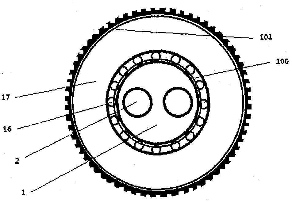
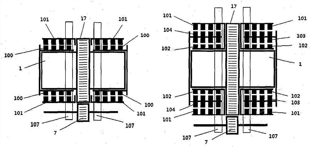
[0071] exist figure 1 Among them, the triangular integral casting cylinder body is integrally cast by the opposed piston cylinder (4), three square columns (3) and a round shaft with two large round holes, and the opposed piston (59) in the cylinder is connected to the connecting rod (10) The gear (7) driving the mixed-flushing and mixed-stroke main transmission shaft (5), the gear (9) of the sub-shaft crankshaft (8) and the flywheel gear (17) of the non-rotating round shaft (1) of the central shaft are meshed In operation, the electromagnetic stator (100) sleeved on the non-rotating round shaft (1) of the central shaft drives each other with the permanent magnet rotors (101) installed on both sides of the bearing (16), and the non-rotating round shaft (1) of the central shaft The axial center horizontal large circular hole (2) is screwed together with the large circular hole on the top surface of the engine fixing bracket arc arched panel (12) and the large circular hole in t...


PUM


Abstract

The invention belongs to the field of electromagnetic or fuel oil hybrid engines subjected to coupling driving by hybrid opposite pistons and hybrid layer rotors and stators, and discloses a cylinderbody structure of a hybrid opposite piston and mixed layer rotor and stator engine. According to the cylinder body structure, conflict of installation space of an opposite piston shaft coupling engineand an existing engine is solved; a crankshaft of a split shaft of a triangle external gear pump coupling engine serves as a cylinder body structure of a main transmission shaft, so that the problemthat the explosive force of an electromagnetic engine is not high is solved; and moreover, an ingenious joint point of an electromagnetic rotor and stator and a hybrid piston is found out. The cylinder structure has the beneficial effects that with no need of changing or just slightly changing the installation structure in the prior art, the compression ratio can be adjusted, and the installationand maintenance are simple and convenient to achieve; and especially, a fuel and electromagnetic double-sided hybrid piston engine, a permanent magnet double-stator electromagnetic piston engine and apermanent magnet three-stator electromagnetic opposite piston coupling engine are invented and applied, an inner meshing gear coupling engine is arranged in a hub to drive a tire to rotate, and an application space is provided for a wheel engine by a concentric circle double helix structure and a fixed shaft structure of an opposite piston inner and outer meshing gear coupling engine.

Description

technical field [0001] The invention belongs to the field of electromagnetic and fuel hybrid engines, in particular to an engine driven by a mixed-layer rotor stator and hybrid opposed pistons. Background technique [0002] Energy conservation and environmental protection are the development direction pursued by the engine field. The oil-fired opposed-piston engine has become the research and development direction of the fuel-oil piston engine with its piston force area, compression stroke, compression ratio coefficient and unique intake and exhaust methods. In order to further meet the requirements of energy saving, emission reduction and green environmental protection, in recent years, the development and application of new energy technologies for environmentally friendly fuels have been explored. Among them, the rotor of the mixed-layer rotor stator electromagnetic engine is driven by a multi-layer lever, and the piston of the fuel electromagnetic double-sided hybrid pisto...

Claims


Application Information

Patent Timeline
Patent Type & Authority Patents(China)
IPC IPC(8): F02B55/02F02B55/08F02B55/10H02K7/18
CPCF02B55/02F02B55/08F02B55/10H02K7/1807
Inventor 陈良昌陈鑫
Owner 辽宁方联发动机有限公司
Why Eureka
Try Eureka