
Light self-climbing shield frame system and construction method thereof

A shielding frame and self-climbing technology, which is applied to the accessories of scaffolding, the scaffolding supported by the building structure, the supporting structure of the building, etc., can solve the cumbersome and heavy cost of the lifting system and the anti-falling device, the difficulty of installation and disassembly, and the cumbersome lifting process, etc. problems, to achieve the effect of saving manpower, fast construction and high insurance factor

Pending Publication Date: 2019-07-23
SHANGHAI CONSTR NO 1 GRP
View PDF7 Cites 6 Cited by
  • Summary
  • Abstract
  • Description
  • Claims
  • Application Information

AI Technical Summary

Problems solved by technology

[0004] In view of the traditional shielding frame system, the lifting system and the anti-falling device are relatively cumbersome and bulky, the cost is high, the installation and disassembly are difficult, the lifting process is cumbersome and the safety is low. The purpose of the present invention is to provide a light self-climbing shielding frame system and Its construction method is to realize the renewal of the shielding frame system and meet the construction requirements of increasingly complex super high-rise buildings

Method used


Image

  • Light self-climbing shield frame system and construction method thereof
  • Light self-climbing shield frame system and construction method thereof
  • Light self-climbing shield frame system and construction method thereof

Examples


Embodiment 1

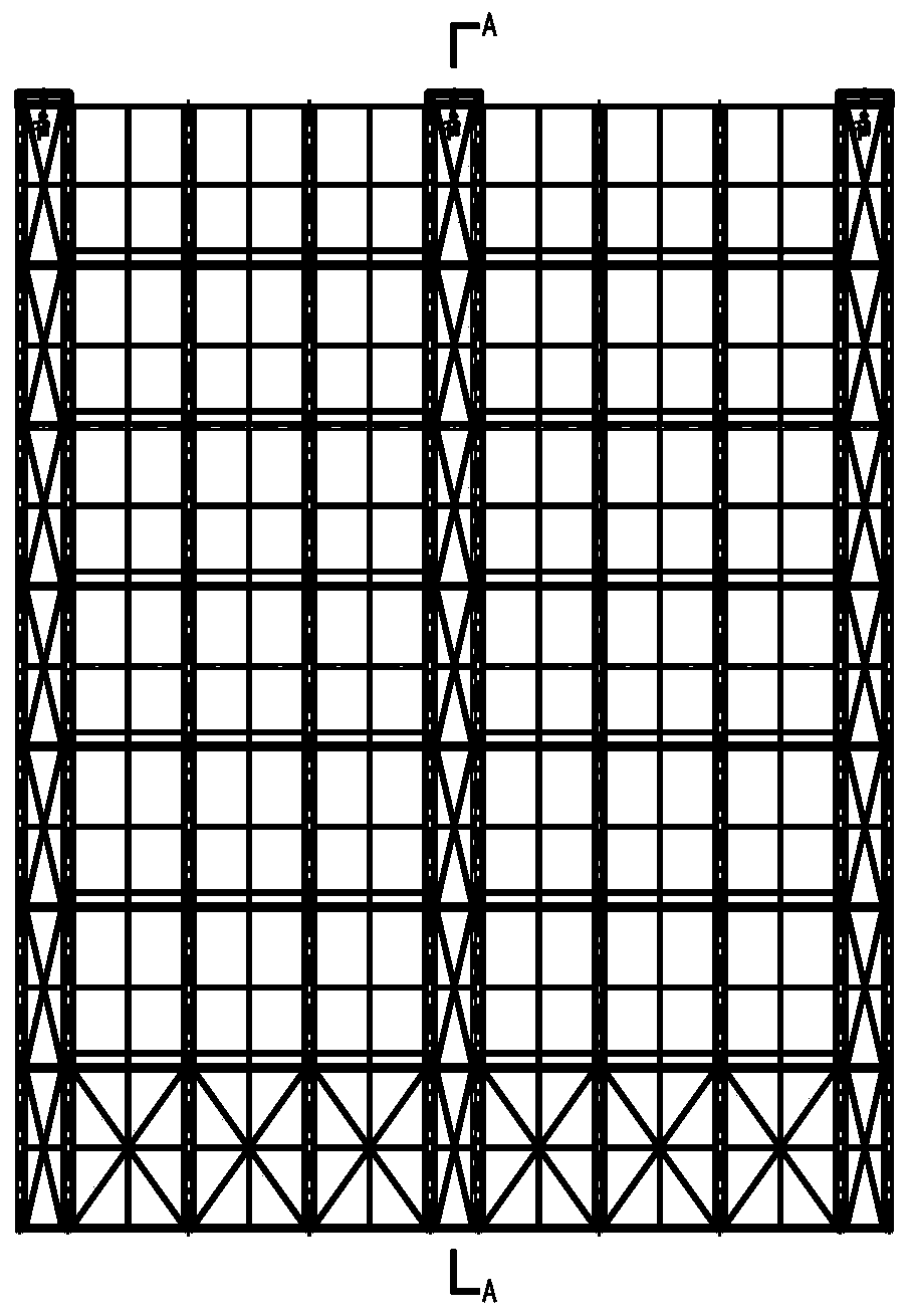
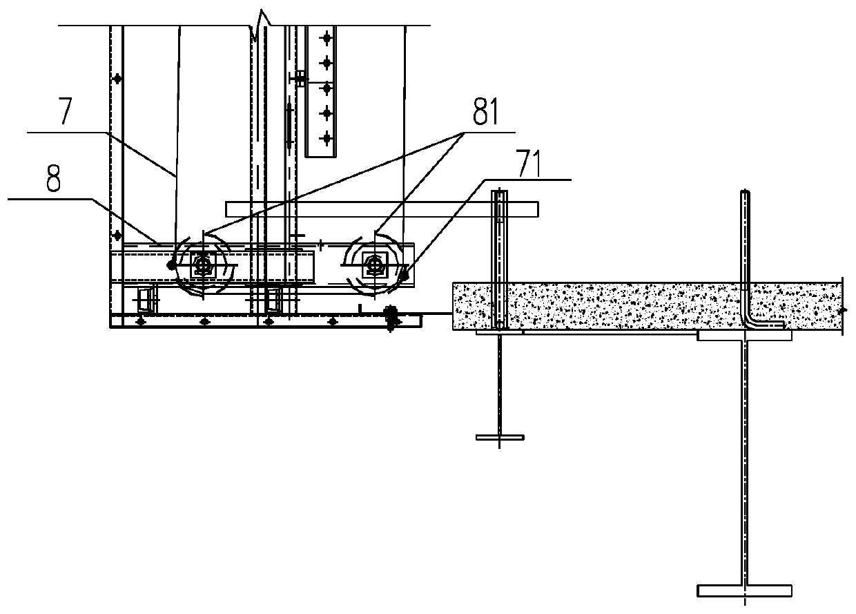
[0039] combine Figure 1 to Figure 7 Describe the structural composition of the lightweight self-climbing shielding frame system of the present invention.

[0040] Please refer to Figure 1 to Figure 7 , a light self-climbing shielding frame system, including a scaffolding system 1, a support system, a lifting system, and an anti-tilt and anti-drop system; the support system includes a load-bearing frame and an oblique load-bearing pull The connecting plate 3 and the rear frame body 4, the rear frame body 4 is fixed on the structural steel beam 5 through embedded parts, the middle connecting plate 3 is vertically arranged, the front frame body 2 and the rear frame body 4 pass through the middle connecting plate 3 fixed connection; the lifting system includes an electric hoist, a lifting wire rope 7 and a bottom guide wheel 81, the electric hoist is fixed on the top of the scaffolding system 1, the bottom guide wheel 81 is fixed on the bottom of the scaffolding system 1, one e...


PUM


Abstract

The invention discloses a light self-climbing shield frame system and a construction method thereof, and relates to the technical field of formwork systems. The light self-climbing shield frame systemand the construction method thereof are used for solving the problems of the tedious lifting process of a lifting system and an anti-falling device and low safety. The light self-climbing shield frame system includes a scaffold system, a supporting system, a lifting system and an anti-tilting and anti-falling system. The supporting system includes a bearing frame which is fixed on a structural steel beam; the lifting system includes an electric block, a bottom guiding wheel and a steel wire rope, wherein the electric block is arranged at the top of the scaffold system, the bottom guiding wheel is fixed to the bottom of the scaffold system, one end of the steel wire rope is connected with the electric block, and the other end of the steel wire rope passes through the bottom guiding wheel to be arranged at the bottom of the bearing frame in a hung mode; the anti-tilting and anti-falling system includes a guiding rail installed on a scaffold frame body, and an anti-falling pawl wheel, alimiting spring, an anti-falling pawl and a limiting baffle are arranged on the bearing frame; the anti-falling pawl wheel meshes with the guiding rail, the limiting spring is used for limiting the stroke of the anti-falling pawl, and the anti-falling pawl and the limiting baffle are used for preventing the anti-falling pawl wheel from rotating counterclockwise. Therefore, falling of the scaffoldframe body and the guiding rail is prevented, and the anti-falling effect is achieved advantageously.

Description

technical field [0001] The invention relates to the technical field of formwork systems, in particular to a light self-climbing shielding frame system and a construction method thereof. Background technique [0002] The traditional shielding frame system, the lifting system and the anti-falling device are relatively cumbersome and cumbersome, resulting in a large overall size of the overall frame (the width generally reaches more than 800mm, and the height generally covers 4 floors), resulting in a large increase in the amount of steel used for the frame body, and the self-weight also increases. The increase will bring about a series of problems such as increased cost, difficulty in installation and disassembly, cumbersome lifting process and low safety, etc. It is difficult to meet the needs of today's super high-rise construction and the requirements of green construction. [0003] The lifting system of the traditional shielding frame system generally uses the climbing fra...

Claims


Application Information

Patent Timeline
Patent Type & Authority Applications(China)
IPC IPC(8): E04G3/30E04G3/32E04G5/00E04G21/00
CPCE04G3/30E04G3/32E04G3/325E04G5/001E04G21/00E04G2003/286
Inventor 朱毅敏徐磊陆庆华曹建中黄滔陈逯浩
Owner SHANGHAI CONSTR NO 1 GRP
Learn More