Automatic debonding machine

A combined and automatic technology, applied in microstructure devices, microstructure technology, etc., can solve the problems of substrate fragmentation and inability to complete substrate separation, and achieve the effect of improving the success rate

Pending Publication Date: 2019-07-23
SUZHOU MEMSTOOLS SEMICON TECH CO LTD
View PDF0 Cites 0 Cited by
  • Summary
  • Abstract
  • Description
  • Claims
  • Application Information

AI Technical Summary

Problems solved by technology

During the debonding process, the upper and lower suction cups must always be parallel, otherwise the substrate will be broken or the substrate separation will not be completed. The current debonding machine is difficult to meet the needs of the debonding process.

Method used


Image

  • Automatic debonding machine
  • Automatic debonding machine
  • Automatic debonding machine

Examples


Embodiment Construction

[0024] The present invention will be further described below in conjunction with specific drawings and embodiments.

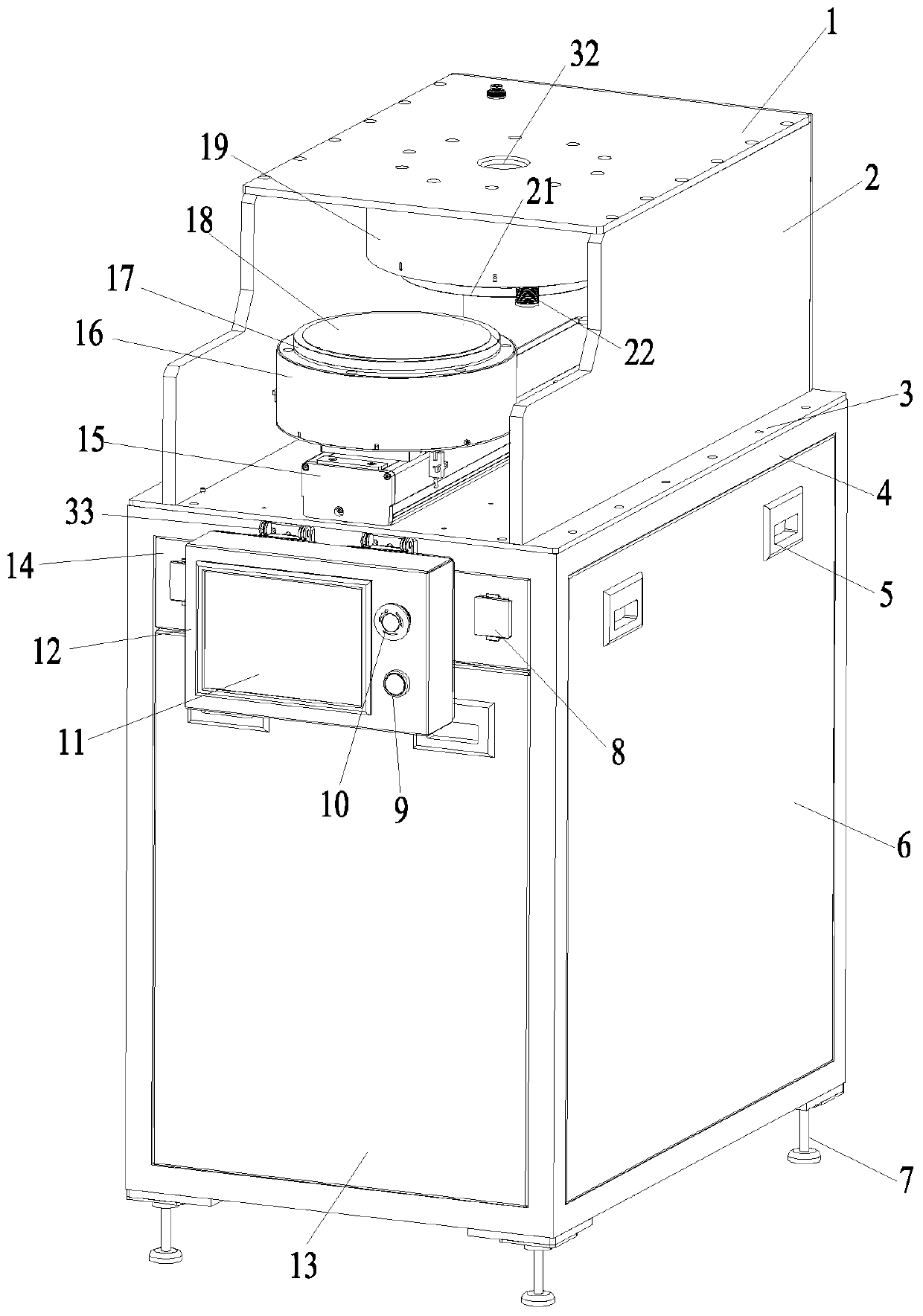
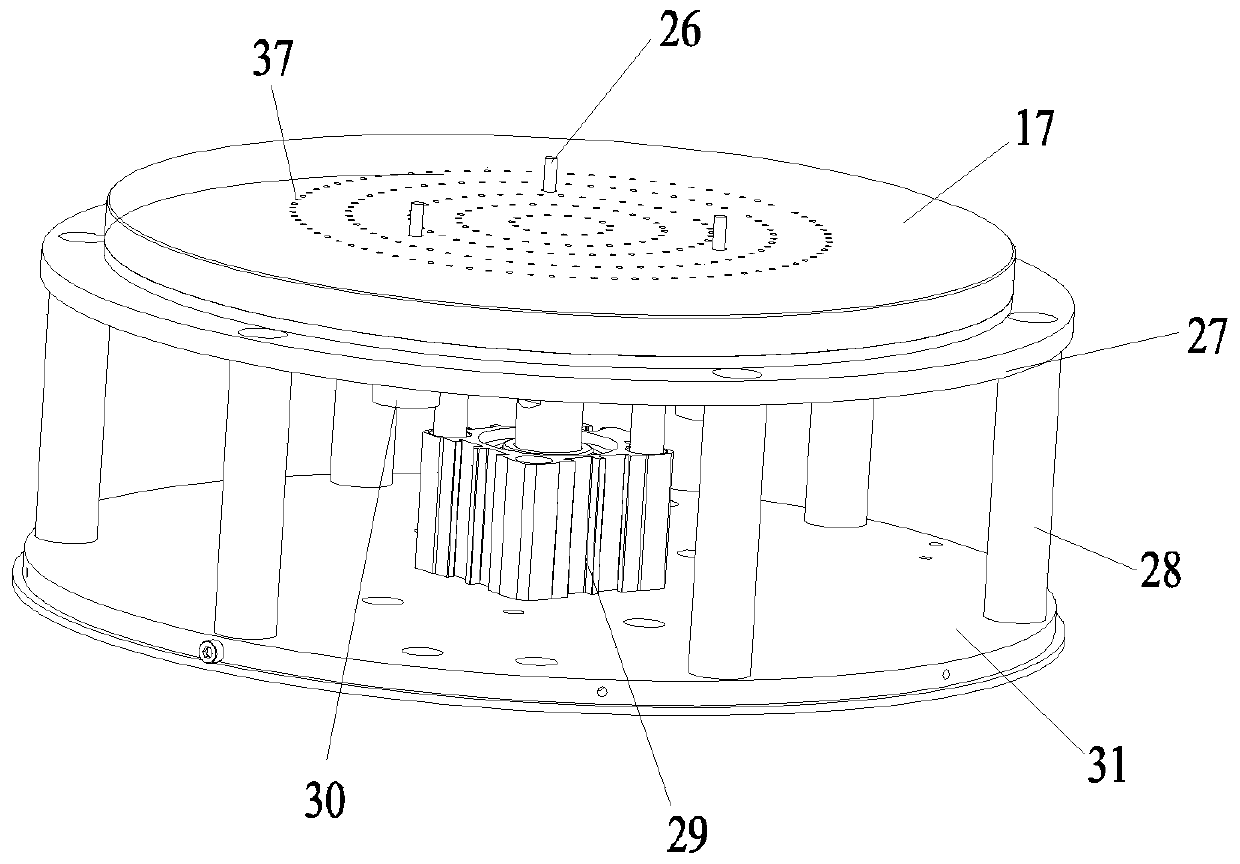
[0025] Such as figure 1 , figure 2 with image 3 As shown: in order to effectively ensure the parallelism between the upper vacuum chuck 21 and the lower vacuum chuck 17 during the debonding process and improve the success rate of debonding, the present invention includes a casing, and a bonding substrate group 18 capable of absorbing bonding is arranged in the casing The substrate adsorption and fixing top sheet device 16 and the substrate adsorption heating device 19 capable of heating the bonded substrate group 18, the substrate adsorption heating device 19 is located at the upper part of the casing, and the substrate adsorption and fixing top sheet device 16 is installed in the lower part of the casing through the manipulator 15, and the substrate adsorption and fixed top sheet device 16 can move to the right below the substrate adsorption heating device...


PUM


Abstract

The invention relates to an automatic debonding machine. A substrate adsorption heating device comprises an upper connecting plate, an upper vacuum chuck arranged on the lower side surface of the upper connecting plate, and a welding corrugated pipe arranged on the upper side surface of the upper connecting plate. The welding corrugated pipe is inflated; the upper vacuum chuck can be driven to move towards the substrate adsorption fixing top sheet device close to the lower part through the extension of the welding corrugated pipe; after the upper vacuum chuck is in contact with a bonding substrate set on the substrate adsorption fixing top piece device, the bonding substrate set can be heated through the upper vacuum chuck until the bonding substrate set is debonded, a lower substrate obtained after debonding can be adsorbed to the substrate adsorption fixing top piece device, and an upper substrate obtained after debonding can be adsorbed to the upper vacuum chuck. The debonding device is compact in structure, can effectively ensure that the upper vacuum chuck and the lower vacuum chuck are parallel in the debonding process, improves the success rate of debonding, and is safe andreliable.

Description

technical field [0001] The invention relates to a debonding machine, in particular to an automatic debonding machine, which belongs to the technical field of micro-nano. Background technique [0002] In the field of MEMS, debonding is a commonly used processing method. Usually, the substrates that have been glued together are separated by thermal sliding to re-separate the two substrates. During the debonding process, it is necessary to ensure that the upper and lower suction cups are parallel, otherwise the substrate will be broken or the substrate separation will not be completed. The current debonding machine is difficult to meet the needs of the debonding process. Contents of the invention [0003] The purpose of the present invention is to overcome the deficiencies in the prior art and provide an automatic debonding machine with a compact structure, which can effectively ensure the parallelism between the upper vacuum chuck and the lower vacuum chuck during the debond...

Claims


Application Information

Patent Timeline
IPC IPC(8): B81C99/00
CPCB81C99/001
Inventor 王云翔冒薇段仲伟马冬月许爱玲李晓帅祝翠梅姚园
Owner SUZHOU MEMSTOOLS SEMICON TECH CO LTD
Why Eureka
Try Eureka