Portable Trace Angle and Length Acquisition Device
A collection device and portable technology, applied in the field of trace identification, can solve the problems of inaccurate identification results, the secondary collision of tire scratches becoming larger and longer, and the identification results being hindered, so as to achieve the effect of improving authenticity and measurement accuracy.
- Summary
- Abstract
- Description
- Claims
- Application Information
AI Technical Summary
Problems solved by technology
Method used
Image
Examples
Embodiment approach 1
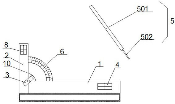
[0034]This embodiment provides a portable trace angle and length acquisition device, such as image 3 As shown, it is mainly composed of a horizontal base 1, a vertical base 2, a laser transmitter 3, a bubble level alignment device 4, a bubble vertical alignment device 8, a target ruler 5 and an angle steering wheel 6 made of transparent material. The vertical base 2. It is vertically and fixedly connected to one end of the horizontal base 1. The bubble level aligner 4 is fixed on the horizontal base 1. The bubble vertical aligner 8 is fixed on the vertical base 2. The angle steering wheel 6 is fixed on the horizontal base 1 and the vertical base. Between the angles of the base 2, the laser emitter 3 is rotatably connected to the intersection of the horizontal base 1 and the vertical base 2, and the laser emitter 3 and the angle steering wheel 6 are located in the same plane; the target ruler 5 is facing The laser emission direction setting of the laser transmitter 3, such as ...
Embodiment approach 2
[0038] This embodiment is a further improvement of Embodiment 1. The main improvement is that in Embodiment 1, the rotation of the laser emitter 3 is manually rotated, and its angle control is not precise and stable enough, which will lead to low measurement efficiency and low measurement accuracy. low, and in this embodiment, the angle adjustment mechanism 7 for adjusting the rotation angle of the laser emitter is also provided in the portable trace angle and length acquisition device, and the angle of the laser emitter 3 can be stabilized by the angle adjustment mechanism 7 Precise control and adjustment can effectively guarantee the measurement accuracy and measurement efficiency of the device.
[0039] Specifically, as shown in Figures 6 to 8, the above-mentioned angle adjustment mechanism 7 is mainly composed of a coarse adjustment nut 701, a coarse adjustment worm 702, an adjustment worm wheel 703 and a transmitter direction changing gear 704. The coarse adjustment nut 70...
Embodiment approach 3
[0042] This embodiment is a further improvement of Embodiment 2, the main improvement is that in this embodiment, as Figure 9 and 10 , the angle adjustment mechanism 7 also includes a fine-tuning nut 705 and a fine-tuning worm 706, the fine-tuning nut 705 is rotationally connected with the vertical base 2, the fine-tuning worm 706 is slidingly connected with the vertical base 2, and the thread of the fine-tuning nut 705 is engaged with one end of the fine-tuning worm 706 , the other end of the fine-tuning worm 706 is engaged with the adjusting worm wheel 703 . When the fine-tuning nut 705 is rotated, the fine-tuning worm 706 is passed to drive the adjustment worm gear 703 to rotate, and finally the transmitter direction-changing gear 704 and the laser transmitter 3 on it are driven to rotate, and the angle of the laser transmitter 3 is fine-tuned through the fine-tuning nut 705. This makes the angle adjustment of the laser transmitter 3 more precise and controllable, ensurin...
PUM
 Abstract
Description
Claims
Application Information
 - R&D
- Intellectual Property
- Life Sciences
- Materials
- Tech Scout
- Unparalleled Data Quality
- Higher Quality Content
- 60% Fewer Hallucinations
Browse by: Latest US Patents, China's latest patents, Technical Efficacy Thesaurus, Application Domain, Technology Topic, Popular Technical Reports.
© 2025 PatSnap. All rights reserved.Legal|Privacy policy|Modern Slavery Act Transparency Statement|Sitemap|About US| Contact US: help@patsnap.com


