
Portable trace angle and length collecting device

A collection device and portable technology, applied in the field of trace identification, can solve the problems of inaccurate identification results, obstruction of identification results, incomplete identification methods, and accurate recording of accident scene information, etc., to achieve the effect of improving authenticity and measurement accuracy

Active Publication Date: 2019-07-19
HUAIYIN INSTITUTE OF TECHNOLOGY
View PDF21 Cites 0 Cited by
  • Summary
  • Abstract
  • Description
  • Claims
  • Application Information

AI Technical Summary

Problems solved by technology

[0005] 1. In the process of moving the accident vehicle to the appraisal office, its state at the accident scene will inevitably be changed, such as the direction of traces and other information, which will cause certain obstacles to the subsequent appraisal results
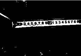
[0006] 2. In the process of moving the accident vehicle to the appraisal office, some collisions may occur, changing the length, size and other key information of the trace, such as Figure 1 The tire scratches in the test are very likely to become larger and longer due to secondary collisions, resulting in inaccurate identification results
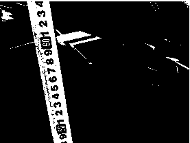
[0007] Visual observations compared with a tape measure are not accurate enough, and it is impossible to judge the actual direction of the trace, such as Figure II The angle at which the horizontal scratch marks are seen on the rear of the electric vehicle body guard panel makes the existing identification methods unable to completely and accurately record the accident scene information

Method used


Image

  • Portable trace angle and length collecting device
  • Portable trace angle and length collecting device
  • Portable trace angle and length collecting device

Examples


Embodiment approach 1

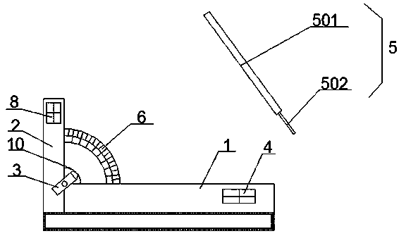
[0034]This embodiment provides a portable trace angle and length acquisition device, such as image 3 As shown, it is mainly composed of a horizontal base 1, a vertical base 2, a laser transmitter 3, a bubble level alignment device 4, a bubble vertical alignment device 8, a target ruler 5 and an angle steering wheel 6 made of transparent material. The vertical base 2. It is vertically and fixedly connected to one end of the horizontal base 1. The bubble level aligner 4 is fixed on the horizontal base 1. The bubble vertical aligner 8 is fixed on the vertical base 2. The angle steering wheel 6 is fixed on the horizontal base 1 and the vertical base. Between the angles of the base 2, the laser emitter 3 is rotatably connected to the intersection of the horizontal base 1 and the vertical base 2, and the laser emitter 3 and the angle steering wheel 6 are located in the same plane; the target ruler 5 is facing The laser emission direction setting of the laser transmitter 3, such as ...

Embodiment approach 2

[0038] This embodiment is a further improvement of Embodiment 1. The main improvement is that in Embodiment 1, the rotation of the laser emitter 3 is manually rotated, and its angle control is not precise and stable enough, which will lead to low measurement efficiency and low measurement accuracy. low, and in this embodiment, the angle adjustment mechanism 7 for adjusting the rotation angle of the laser emitter is also provided in the portable trace angle and length acquisition device, and the angle of the laser emitter 3 can be stabilized by the angle adjustment mechanism 7 Precise control and adjustment can effectively guarantee the measurement accuracy and measurement efficiency of the device.

[0039] Specifically, as shown in Figures 6 to 8, the above-mentioned angle adjustment mechanism 7 is mainly composed of a coarse adjustment nut 701, a coarse adjustment worm 702, an adjustment worm wheel 703 and a transmitter direction changing gear 704. The coarse adjustment nut 70...

Embodiment approach 3

[0042] This embodiment is a further improvement of Embodiment 2, the main improvement is that in this embodiment, as Figure 9 with 10 , the angle adjustment mechanism 7 also includes a fine-tuning nut 705 and a fine-tuning worm 706, the fine-tuning nut 705 is rotationally connected with the vertical base 2, the fine-tuning worm 706 is slidingly connected with the vertical base 2, and the thread of the fine-tuning nut 705 is engaged with one end of the fine-tuning worm 706 , the other end of the fine-tuning worm 706 is engaged with the adjusting worm wheel 703 . When the fine-tuning nut 705 is rotated, the fine-tuning worm 706 is passed to drive the adjustment worm gear 703 to rotate, and finally the transmitter direction-changing gear 704 and the laser transmitter 3 on it are driven to rotate, and the angle of the laser transmitter 3 is fine-tuned through the fine-tuning nut 705. This makes the angle adjustment of the laser transmitter 3 more precise and controllable, ensuri...


PUM


Abstract

The invention relates to the technical field of trace identification, and discloses a portable trace angle and length collecting device. A vertical base (2) is vertically fixed to one end of a horizontal base (1); a bubble level aligner (4) is fixed on the horizontal base (1); an angle steering wheel (6) is fixed between the angle between the horizontal base (1) and the vertical base (2); a laseremitter (3) is rotatably connected at the intersection joint of the horizontal base (1) and the vertical base (2), and the laser emitter (3) is in the same plane as the angle steering wheel (6); a target ruler (5) is arranged directly facing the laser emission direction of the laser emitter (3); and the angle steering wheel (6) is located between the laser emitter (3) and the target ruler (5). Compared with the prior art, the invention can accurately collect the angle information of the trace directly on the spot, and complete the angle measurement between the trace and the horizontal or vertical plane which could not be completed on the spot.

Description

technical field [0001] The invention relates to the technical field of trace identification, in particular to a portable trace angle and length acquisition device. Background technique [0002] The inspection and identification of the main traces and physical evidence related to the accident provides evidence for the determination of accident responsibility. For the traces and physical evidence extracted, by observing the freshness of the traces, recording the shape, size, height and direction of the traces, looking for the corresponding relationship between the traces, analyzing the formation process of the traces, and judging the relationship between the traces and the accident (whether it was caused by the accident or not) produced), and come to the same identification or inspection opinion or negative conclusion. In the inspection of traces of traffic accidents, most of them belong to types, such as the inspection of paint, rubber and other attachments, collision marks ...

Claims


Application Information

Patent Timeline
IPC IPC(8): G01B11/02G01B11/26
CPCG01B11/02G01B11/26
Inventor 蒋素琴金伟进李伯奎李祥冯清付江振飞汤鹏
Owner HUAIYIN INSTITUTE OF TECHNOLOGY
Learn More