Method for detecting the movement of a temporomandibular joint

A technology of temporomandibular joint and jaw, applied in the field of movement of temporomandibular joint, can solve the problems of unable to display soft tissue, a lot of time and so on

Active Publication Date: 2019-07-16
SIRONA DENTAL SYSTEMS
View PDF5 Cites 3 Cited by
  • Summary
  • Abstract
  • Description
  • Claims
  • Application Information

AI Technical Summary

Problems solved by technology

[0003] However, the downside is that the radiation is exposed from the DVT scan, which cannot show soft tissues and takes a lot of time

Method used


Image

  • Method for detecting the movement of a temporomandibular joint
  • Method for detecting the movement of a temporomandibular joint
  • Method for detecting the movement of a temporomandibular joint

Examples


Embodiment Construction

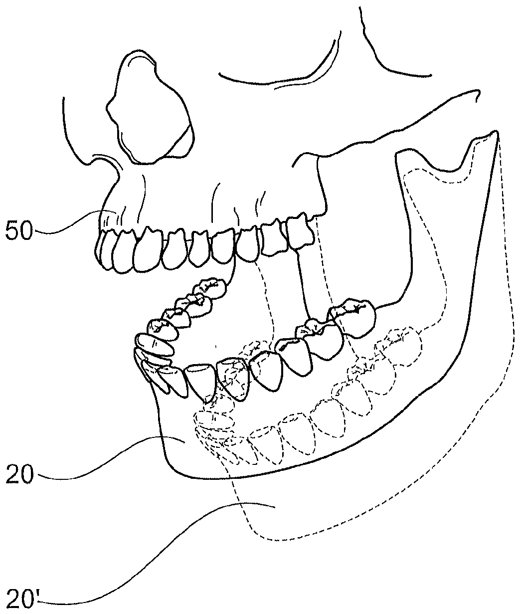
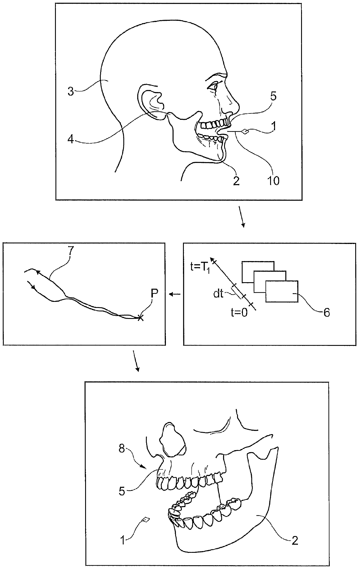
[0047] figure 1 A sketch showing the method steps of the method according to the invention according to a first embodiment. Firstly, the marker 1 is fixed to the lower jaw 2 of the patient 3 by means of the fixing member 10 . Marker 1 consists of material visible on MRI. In the illustrated design example, the fixing member 10 is an occlusal tray fixed to the teeth of the lower jaw 2 by means of an adhesive.

[0048] The movement of the marker 1 caused by the movement of the temporomandibular joint 4 is then measured using a magnetic resonance imaging device (not depicted), wherein the lower jaw 2 , upper jaw 5 and marker 1 are located and measured in the recording volume of the recording device. To this end, during a first measurement time interval T1 a plurality of measurement data sets 6 are generated within a short time interval dt by means of the magnetic resonance imaging device. Subsequently, on the basis of each measurement data set 6 , the three-dimensional position...


PUM


Abstract

The invention relates to a method for detecting and displaying the movement of a temporomandibular joint (4) which connects a lower jaw (2) and an upper jaw (5) by means of magnetic resonance imaging.A marker (1) is secured to the lower jaw (2), a marker movement curve (7) is generated using magnetic resonance imaging measurement data sets (6) during a first measurement interval (T1), during which the lower jaw (2) is moved relative to the upper jaw (5), and a point which corresponds to a first position (P1) of the lower jaw (4) relative to the upper jaw (5) is ascertained on the movement curve. An image data set (8) is generated during a second measurement interval (T2), during which the temporomandibular joint (4) is not moved, and a first model (50), which represents at least one partof the upper jaw and / or a temporal bone part that comprises the temporomandibular joint socket, and a second model (20), which represents at least one part of the lower jaw, are ascertained therefrom.A movement curve of the second model (20, 20') relative to the first model (50) is calculated and displayed using the marker movement curve (7).

Description

technical field [0001] The invention relates to a method for detecting and displaying movements of a patient's temporomandibular joint, which connects the lower jaw and the upper jaw, by means of magnetic resonance imaging. Background technique [0002] For example, typical methods for detecting and observing movement of the temporomandibular joint, such as those used for diagnosing craniomandibular dysfunction, combine movement data from coaxial illumination scans with image data from DVT scans. The visualizations thus obtained are also frequently supplemented with data from surface scans. [0003] However, the downside is that exposure to radiation comes from a DVT scan, which cannot show soft tissues and takes a lot of time. [0004] A method for tracking a patient's head movement during an MRI scan of the head using inductively coupled marker coils is known from S. Sengupta et al. Correction (Prospective Real Time Head Motion Correction Using Inductively Coupled Wirele...

Claims


Application Information

Patent Timeline
Patent Type & Authority Applications(China)
IPC IPC(8): A61C19/045G01R33/24A61B6/14A61B8/13
CPCA61B5/055A61B5/1127A61B5/4542A61C19/045A61B2090/3958G01R33/5608G01R33/56308G01R33/58A61B5/004A61B5/1122A61B6/505A61B90/39A61B2090/3933A61B2090/3966A61B2090/3991
Inventor V.拉舍S.旺德拉克
Owner SIRONA DENTAL SYSTEMS
Why Eureka
Try Eureka