
Lifting appliance and lifting method

A hoisting method and spreader technology, applied in the field of spreaders, can solve problems such as poor equipment stability, inability to adjust equipment, poor safety performance, etc., and achieve the effects of stable operation, convenient debugging, and easy use

Pending Publication Date: 2019-07-16
烟台艾森特智能装备有限公司
View PDF0 Cites 17 Cited by
  • Summary
  • Abstract
  • Description
  • Claims
  • Application Information

AI Technical Summary

Problems solved by technology

At present, during the use of the spreader, due to the uncertainty of the center of mass offset of the equipment, the stability of the equipment during the hoisting process is poor, and it cannot be flexibly adjusted according to the offset of the center of mass of the equipment. The safety performance is poor, and it is easy to cause hoisting accidents

Method used


Image

  • Lifting appliance and lifting method
  • Lifting appliance and lifting method
  • Lifting appliance and lifting method

Examples


Embodiment Construction

[0034] In order to make the above objects, features and advantages of the present invention more comprehensible, specific implementations of the present invention will be described in detail below in conjunction with the accompanying drawings. In the following description, numerous specific details are set forth in order to provide a thorough understanding of the present invention. However, the present invention can be implemented in many other ways different from those described here, and those skilled in the art can make similar improvements without departing from the connotation of the present invention, so the present invention is not limited by the specific embodiments disclosed below.

[0035] Unless otherwise defined, all technical and scientific terms used herein have the same meaning as commonly understood by one of ordinary skill in the technical field of the invention. The terminology used herein in the description of the present invention is only for the purpose of...


PUM


Abstract

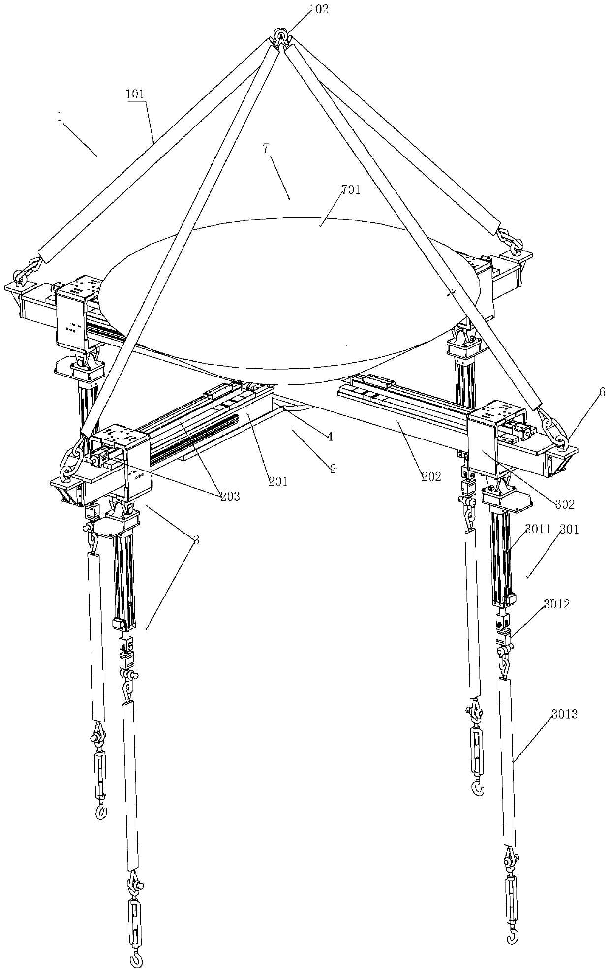
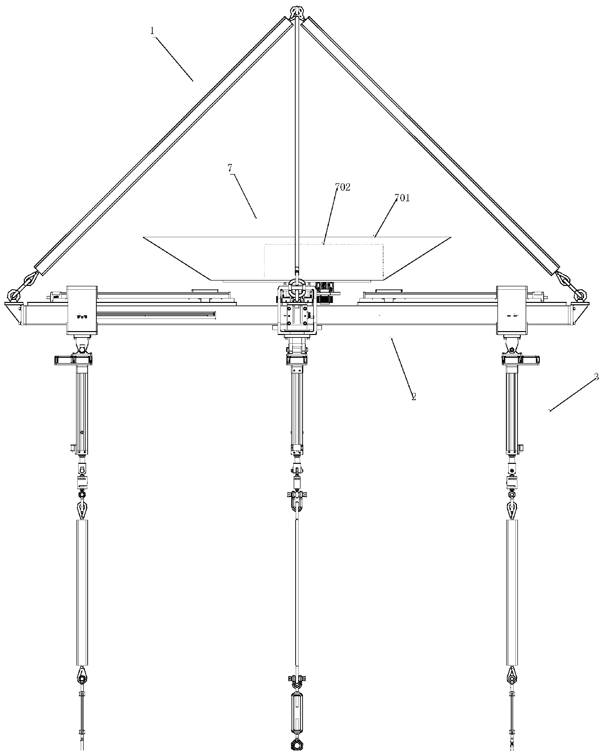
The invention relates to a lifting appliance and a lifting method. The lower ends of multiple belt bodies are connected with the end of a first beam body and the end of a second beam body, the upper ends of the belt bodies are in intersection connection to one point, a through opening is formed in the middle of the first beam body, the second beam body penetrates through the through opening and forms a crossing shape with the first beam body, the second beam body is connected with a driving assembly, the driving assembly enables the first beam body and the second beam body to relatively rotateto change the included angle between the first beam body and the second beam body, a lifting cable body of a lifting cable unit is connected with the first beam body and the second beam body of a lifting beam unit, the lifting cable body slides along the first beam body and the second beam body, the driving assembly comprises a driving motor, a driving gear, a driven gear, a driven shaft and a driving piece, the driving motor is connected with the driving gear, the driving gear is engaged with the driven gear, the driven shaft is connected with the driven gear, the driven shaft penetrates through the second beam body to be connected with the driving piece, the driving piece is located below the through opening, and the two ends of the driving piece are connected with the first beam body.Adjusting capacity is high, the adjusting process is stable, and safety property is reliable.

Description

technical field [0001] The invention relates to a sling and a hoisting method, and relates to the technical field of slings. Background technique [0002] With the rapid development of the machinery industry, the precision requirements of major mechanical conveying tools are constantly improving, and the requirements for errors in the conveying process are becoming more and more stringent. At present, during the use of the spreader, due to the uncertainty of the center of mass offset of the equipment, the stability of the equipment during the hoisting process is poor, and it cannot be flexibly adjusted according to the offset of the center of mass of the equipment. The safety performance is poor, and it is easy to cause hoisting accidents. Contents of the invention [0003] The object of the present invention is to provide a hoisting device and a hoisting method, which are flexible, easy to store, large in rated load, strong in comprehensive horizontal adjustment ability, ...

Claims


Application Information

Patent Timeline
IPC IPC(8): B66C1/14B66C13/08
CPCB66C1/14B66C13/085
Inventor 黄会议刘士亮高倩
Owner 烟台艾森特智能装备有限公司
Learn More