A fully automatic special tape splice and roll change device

A fully automatic and special technology, applied in thin material processing, strip winding, transportation and packaging, etc., can solve the problems of difficult to meet production, inconvenient processing, low production efficiency, etc., to improve production efficiency and prevent docking misalignment , the effect of saving labor and processing costs

Active Publication Date: 2020-11-27
安徽长正升科技有限公司
View PDF9 Cites 0 Cited by
  • Summary
  • Abstract
  • Description
  • Claims
  • Application Information

AI Technical Summary

Problems solved by technology

[0003] The special tape splicing and roll changing device is a device for splicing and changing rolls of special tapes. However, most of the roll changing in the existing tape production is manual operation, which is labor-intensive and time-consuming, resulting in low production efficiency. Most of the tapes are in a messy state when the material receiving device is receiving materials, which is inconvenient for later processing and difficult to meet the needs of production

Method used


Image

  • A fully automatic special tape splice and roll change device
  • A fully automatic special tape splice and roll change device
  • A fully automatic special tape splice and roll change device

Examples


Embodiment 1

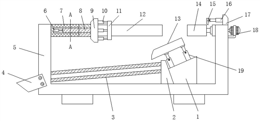
[0025] Embodiment 1, with reference to Figure 1-5 , a full-automatic special tape splicing and changing device, including a device body 5, the device body 5 is a U-shaped structure, a horizontal frame 7 is welded on the inner side of one of the vertical ends of the device body 5, and a connecting frame 7 is clamped inside the horizontal frame 7. One end of the shaft 8 and the connecting shaft 8 is welded with a mounting plate 9, and the center of the side of the mounting plate 9 away from the connecting shaft 8 is welded with an empty reel shaft 12, and the other vertical end of the device body 5 is connected with a winding shaft 14 in rotation on the inner side. One side of the outer wall of the device body 5 is fixed with a winding motor 18 by frame bolts, the output shaft of the winding motor 18 is welded to one end of the winding shaft 14, and the device body 5 is welded with a vertical plate near the vertical end of the winding shaft 14 17. One side of the vertical plate...

Embodiment 2

[0027] Embodiment 2, with reference to figure 1 with Figure 3-5 , there are three material receiving roller shafts 3 in total, and the three material receiving roller shafts 3 are parallel to each other, the three material receiving roller shafts 3 are distributed in an equilateral triangle, two of the three material receiving roller shafts 3 are located at the top, and one Located below, the two receiving roller shafts 3 above are on the same horizontal plane, the inclination angles of the three receiving roller shafts 3 are 15°, the upper surface of the material receiving plate 13 is an arc-shaped structure, and the inclination angle of the material receiving plate 13 is 15°-30°, the center line of the material receiving plate 13, the center line of the reel 14 and the center line of the receiving roller shaft 3 located below are on the same plane, and the reel 14 can be moved up and down through the material receiving plate 13 The adhesive tape is caught and sent to the t...

Embodiment 3

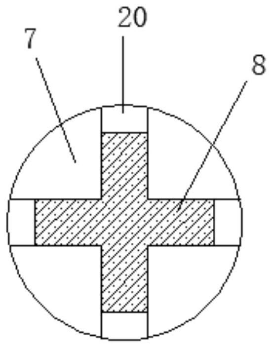
[0028] Embodiment 3, with reference to figure 1 with figure 2 , the bolt on the inner wall of the horizontal frame 7 is fixed with an electric push rod A6, the free end of the electric push rod A6 is welded to one end of the connecting shaft 8, the vertical section of the connecting shaft 8 is a cross-shaped structure, and the horizontal frame 7 is equipped with a Card slot 20, when the electric push rod A6 is running, push the connecting shaft 8 to slide inside the card slot 20, so that the empty roll sleeve shaft 12 moves to the winding shaft 14, so that the empty roll of the tape on the empty roll sleeve shaft 12 moves to the winding shaft 14 On the other hand, the structural arrangement of the cross-shaped shaft 8 makes the sliding in the card slot 20 more stable.


PUM

PropertyMeasurementUnit
angleaaaaaaaaaa

Abstract

The invention discloses a full-automatic special adhesive tape receiving and roll changing device which comprises a device body, wherein the device body is of a U-shaped structure; a cross frame is welded to the inner side of one vertical end of the device body; a connecting shaft is clamped in the cross frame; an installation plate is welded to one end of the connecting shaft; an empty winding sleeve shaft is welded to the center of the side, far away from the connecting shaft, of the installation plate; and a winding shaft is rotatably connected on the inner side of the other vertical end ofthe device body, an output shaft of a winding motor is welded to one end of the winding shaft, a vertical plate is welded to the position, near the upper part of the vertical end of the winding shaft, of the device body, and a coil unwinding plate is connected to one side of the vertical plate through an electric push rod C. The full-automatic special adhesive tape receiving and roll changing device is suitable for changing rolls of adhesive tapes and receiving materials in the production of the adhesive tapes, and the device achieves the effects of automatic roll changing and automatic unwinding the rolls of the adhesive tapes through the mutual matching use of an electric push rod A, an electric push rod B and the electric push rod C.

Description

technical field [0001] The invention belongs to the technical field of adhesive tape production, and in particular relates to a fully automatic special adhesive tape splicing and roll changing device. Background technique [0002] Tape can be divided into high temperature tape, double-sided tape, insulating tape, special tape, pressure sensitive tape, die-cut tape according to its functions. Different functions are suitable for different industry needs. The surface of the tape is coated with a layer of adhesive to To make the tape stick to the object, the earliest adhesives came from animals and plants. In the nineteenth century, rubber was the main component of the adhesive; and in modern times, various polymers are widely used. The tape is composed of two parts: the base material and the adhesive. , two or more unconnected objects are connected together by bonding, and a layer of adhesive is coated on its surface. The earliest adhesive comes from animals and plants. In the...

Claims


Application Information

Patent Timeline
Patent Type & Authority Patents(China)
IPC IPC(8): B65H19/30B65H18/10B65H18/02
CPCB65H18/026B65H18/10B65H19/30B65H19/305B65H2301/417B65H2701/11332
Inventor 凌德根徐华容于海涛
Owner 安徽长正升科技有限公司
Why Eureka
Try Eureka