
Optimal distribution point evaluation method for substation area power quality management equipment

A technology for power quality and optimal distribution, applied in circuit devices, AC network circuits, and multi-phase network asymmetry reduction, etc., can solve problems such as loss impact, increased active power loss of transformers, and reduced output of distribution transformers.

Inactive Publication Date: 2019-07-05
STATE GRID ZHEJIANG ELECTRIC POWER +2
View PDF5 Cites 2 Cited by
  • Summary
  • Abstract
  • Description
  • Claims
  • Application Information

AI Technical Summary

Problems solved by technology

Furthermore, the three-phase four-wire power supply mode is commonly used in the urban and rural low-voltage distribution networks in my country, and the wiring mode of distribution transformers is mostly 10 / 0.4kV step-down and Y / yn0 wiring. The actual power supply network is a three-phase four-wire system. Phase production power consumption and single-phase load power consumption are mixed, coupled with the problem of non-uniform line standards, uncontrollable capacity increase of single-phase users, continuous access of high-power loads, and dispersion of power consumption time of single-phase loads, etc., All are factors that cause unbalanced three-phase load
The unbalanced three-phase load not only easily affects the user voltage and line loss in the station area, but also increases the active power loss of the transformer, makes the operating temperature of the distribution transformer rise abnormally, reduces the output of the distribution transformer, and causes voltage deviation at the center point. Shift, resulting in three-phase voltage asymmetry, causing local voltage to be too high or too low, and in serious cases, it will burn the user's household appliances and production equipment
How to reasonably distribute and configure power quality control equipment has become a key issue, and there is no effective solution for this

Method used


Image

  • Optimal distribution point evaluation method for substation area power quality management equipment
  • Optimal distribution point evaluation method for substation area power quality management equipment

Examples


Embodiment Construction

[0012] In order to understand the above-mentioned purpose, features and advantages of the present invention more clearly, it is attached below that the embodiments of the present application and the features in the embodiments can be combined with each other under the condition of no conflict.

[0013] In the following description, many specific details are set forth in order to fully understand the present invention. However, the present invention can also be implemented in other ways different from those described here. Therefore, the protection scope of the present invention is not limited by the specific details disclosed below. EXAMPLE LIMITATIONS.

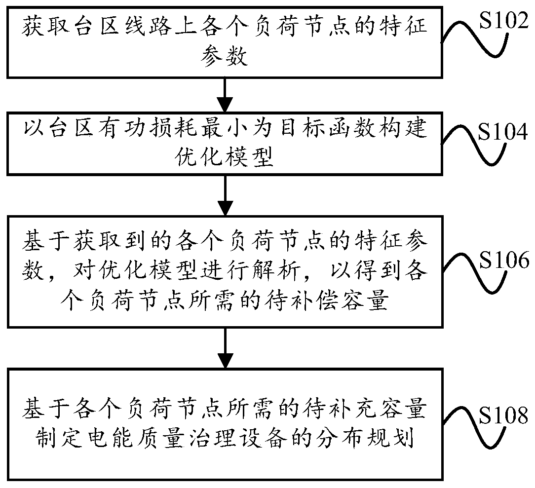
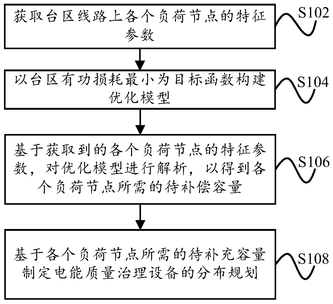
[0014] figure 1 A schematic flowchart of a method for evaluating optimal distribution points of power quality control equipment in a station area according to an embodiment of the present invention is shown.

[0015] Such as figure 1 As shown, according to the embodiment of the present invention, the method for evaluating t...


PUM


Abstract

The invention discloses an optimal distribution point evaluation method for substation area power quality management equipment. The method comprises steps of acquiring the characteristic parameters ofvarious load nodes on a substation area line; constructing an optimization model with an objective function of minimizing the active loss of the substation area; analyzing, based on the acquired characteristic parameters of the respective load nodes, the optimization model to obtain the to-be-compensated capacity required by each load node; and formulating a distribution plan of the power qualitymanagement equipment based on the to-be-compensated capacity required by each load node. The method can reasonably plan the power quality management equipment, reduces the power loss of the substation area, and maintains the three-phase load balance of the substation area power distribution system.

Description

technical field [0001] The invention relates to the technical field of power quality control of distribution networks, in particular to a method for evaluating optimal distribution points of power quality control equipment in a station area. Background technique [0002] With the rapid improvement of the economic level, the electricity consumption of enterprises and individual users is increasing year by year, especially in rural areas, urban-rural fringe areas and other areas with high-speed growth in electricity load. Some distribution transformer areas are affected by geographical location and technical factors. , The three-phase unbalance problem is prominent. Furthermore, the three-phase four-wire power supply mode is commonly used in the urban and rural low-voltage distribution networks in my country, and the wiring mode of distribution transformers is mostly 10 / 0.4kV step-down and Y / yn0 wiring. The actual power supply network is a three-phase four-wire system. Phase p...

Claims


Application Information

Patent Timeline
Patent Type & Authority Applications(China)
IPC IPC(8): H02J3/26
CPCH02J3/26H02J2203/20Y02E40/50
Inventor 徐重酉陈蕾聂峥彭勇章毅郭瑜戴晓红汤雍宓天洲秦如意朱圣盼魏洁江灏
Owner STATE GRID ZHEJIANG ELECTRIC POWER
Learn More