
Masonry structure with coal charging hole, smoke guide hole or ascending pipe hole

A technology of masonry structure and coal charging holes, which is applied in the direction of coke oven bricklaying operations, etc., can solve the problems of cracking and collapsing of overhead bricks, cracking of overhead bricks, collapse of carbonization chamber, etc., and achieves easy manufacturing and masonry strength. High, simple structure

Pending Publication Date: 2019-07-05
ACRE COKING & REFRACTORY ENG CONSULTING CORP DALIAN MCC
View PDF0 Cites 0 Cited by
  • Summary
  • Abstract
  • Description
  • Claims
  • Application Information

AI Technical Summary

Problems solved by technology

[0004] The width of the carbonization chamber of small coke ovens is small, and the strength requirements for overhead bricks are not high. The design of using one roof brick at the bottom of the masonry of the smoke hole or the riser pipe hole is obviously no longer applicable; and the size of the roof brick is too large and too heavy to be conducive to construction, which will not only increase the difficulty of transportation and masonry construction, but also is not conducive to fire resistance. The molding and firing of bricks; in addition, a single cuboid-shaped over-the-top brick is prone to transverse cracks during use, resulting in a decrease in yield; in severe cases, the over-the-top brick will break and collapse, resulting in the top of the carbonization chamber and the furnace roof area. collapse
In addition, when the wet coal with moisture is in contact with the high-temperature silica bricks during coal charging, the rapid cooling and rapid heating will also cause breakage and damage to the overhead bricks at the bottom of the coal charging hole, smoke guide hole or riser hole masonry

Method used


Image

  • Masonry structure with coal charging hole, smoke guide hole or ascending pipe hole
  • Masonry structure with coal charging hole, smoke guide hole or ascending pipe hole
  • Masonry structure with coal charging hole, smoke guide hole or ascending pipe hole

Examples


Embodiment Construction

[0019] The specific embodiment of the present invention will be further described below in conjunction with accompanying drawing:

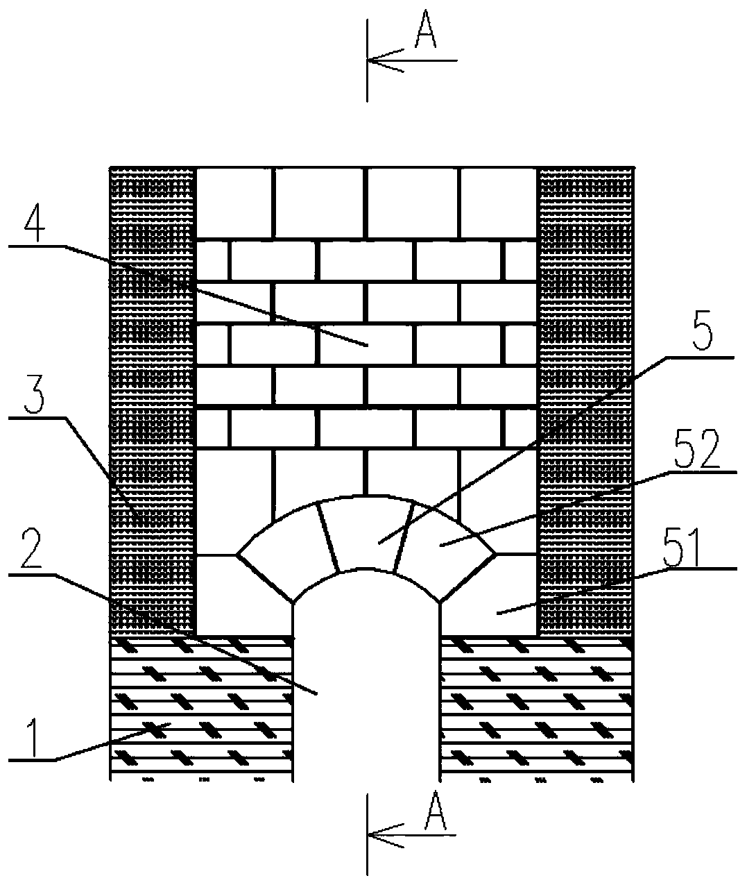
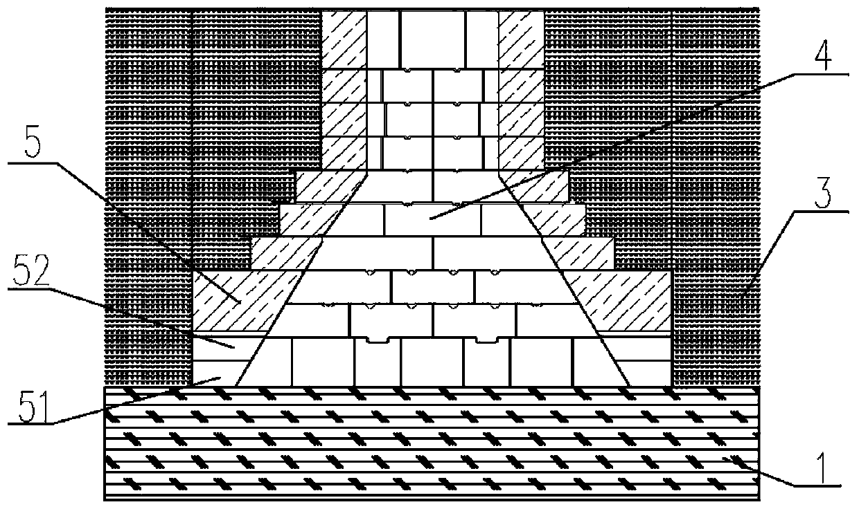
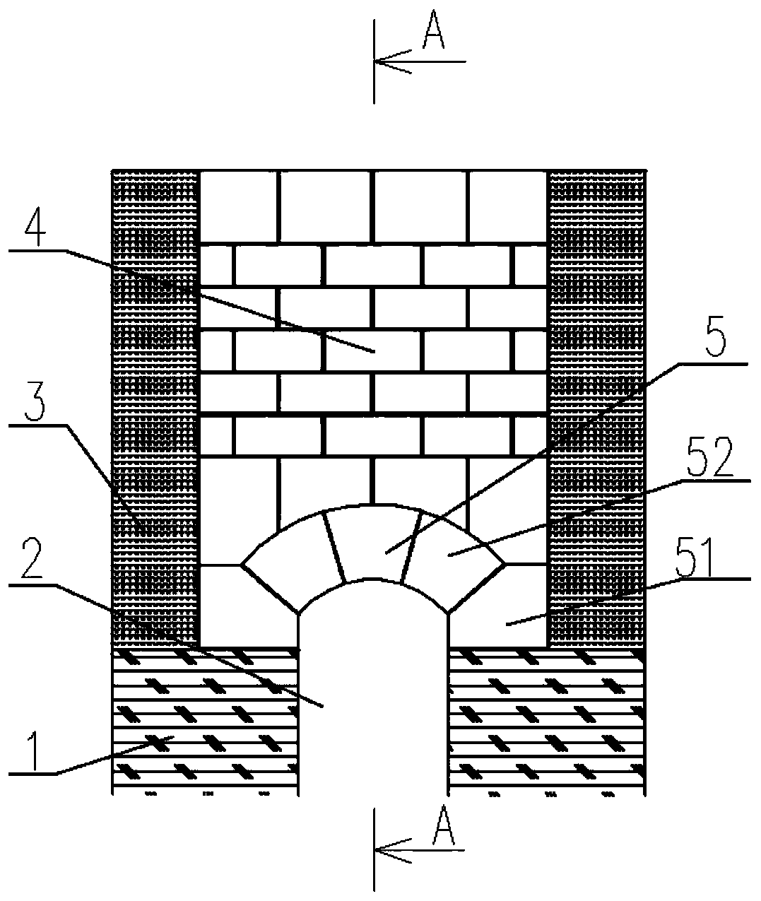
[0020] Such as figure 1 , figure 2 As shown, the masonry structure of a coal charging hole, smoke guiding hole or rising pipe hole according to the present invention includes a coal charging hole masonry, a smoke guiding hole masonry or a rising pipe made of multi-layer refractory bricks. Hole masonry, hereinafter collectively referred to as masonry 4; the bottom of said masonry 4 is an arched structure 5 composed of arched bricks 51 and wedge-shaped bricks 52, and arched bricks 51 are built on both sides of the arched structure 5, The tops of the two combustion chambers 1 located on both sides of the corresponding carbonization chamber 2 respectively, and the middle part of the arched structure 5 is built with wedge-shaped bricks 52 , and the wedge-shaped bricks 52 are located above the corresponding carbonization chamber 2 .

[0021] The arch...


PUM


Abstract

The invention relates to a masonry structure of a coal charging hole, a smoke guiding hole or an ascending pipe hole. The masonry structure comprises a coal charging hole masonry, a smoke guiding holemasonry or an ascending pipe hole masonry which is built by a plurality of layers of refractory bricks, and the masonries are collectively referred to as the masonry below. The bottom of the masonryis an arch structure composed of arch foot bricks and wedge-shaped bricks, the arch foot bricks are built on two sides of the arch structure and are respectively located at the tops of two combustionchambers on two sides of a corresponding carbonization chamber, the wedge-shaped bricks are built in the middle of the arch structure, and the wedge-shaped bricks are located above the corresponding carbonization chamber. The masonry structure has a simple structure, can conveniently and quickly complete the masonry work of the coal charging hole masonry, the smoke guide hole masonry or the ascending pipe hole masonry, has high masonry strength and is suitable for large coke ovens with large carbonization chamber widths.

Description

technical field [0001] The invention relates to the technical field of coke oven body masonry, in particular to a masonry structure of a coal charging hole, a smoke guide hole or a rising pipe hole. Background technique [0002] The main structure of the coke oven body is composed of a carbonization chamber, a combustion chamber, a regenerator, a chute and a roof area. The carbonization chamber is the place where the coal is separated from the air for carbonization, and the combustion chamber is the place where the gas is burned. [0003] The masonry of the coal charging hole, smoke guide hole or riser pipe hole is located in the furnace roof area, and the bottom of the masonry is located on the top of the carbonization chamber. It is usually built in the form of over-the-top bricks, that is, a rectangular-shaped over-the-top brick spans the carbonization chamber. In the width direction of the chamber, the two ends of the overhead brick are placed on the tops of the two adj...

Claims


Application Information

Patent Timeline
Patent Type & Authority Applications(China)
IPC IPC(8): C10B29/02
CPCC10B29/02
Inventor 耿宁严国华韩龙杨俊峰
Owner ACRE COKING & REFRACTORY ENG CONSULTING CORP DALIAN MCC
Learn More