
Jet membrane method internal circulation reactor and sewage treatment method thereof

A technology of internal circulation and reactor, which is applied in the field of jet film internal circulation reactor and its sewage treatment, which can solve the problems of insufficient air mass transfer of sewage and sludge, small internal circulation volume and reflux ratio, and inability to realize internal circulation, etc. , to achieve the effect of convenient automatic operation and management, improved processing effect and simple structure

Pending Publication Date: 2019-07-05
HAINAN TIANHONG MUNICIPAL DESIGN CO LTD
View PDF10 Cites 0 Cited by
  • Summary
  • Abstract
  • Description
  • Claims
  • Application Information

AI Technical Summary

Problems solved by technology

This patent is mainly to entrain air after the pressurized part of the sludge is sprayed by the ejector. The main disadvantages of this method are: 1. Large power consumption; 2. Insufficient mass transfer between sewage and sludge air, and the treatment effect is not good ; 3. Insufficient oxygen supply; 4. Small internal circulation and reflux ratio
The main disadvantage of this patent is that the height of the cylinder is high (up to about 7m), the structure is complex, the power consumption is large, the management is inconvenient, and the internal circulation cannot be realized when the concentration of sewage is low.

Method used


Image

  • Jet membrane method internal circulation reactor and sewage treatment method thereof
  • Jet membrane method internal circulation reactor and sewage treatment method thereof
  • Jet membrane method internal circulation reactor and sewage treatment method thereof

Examples


Embodiment Construction

[0039] The present invention will be further described below in conjunction with the accompanying drawings and embodiments.

[0040] The structures, proportions, sizes, etc. shown in the drawings attached to this specification are only used to match the content disclosed in the specification for the understanding and reading of those who are familiar with this technology, and are not used to limit the conditions for the implementation of the present invention , so it has no technical substantive meaning, and any modification of structure, change of proportional relationship or adjustment of size shall still fall within the scope of the disclosure of the present invention without affecting the functions and objectives of the present invention. The technical content must be within the scope covered. At the same time, terms such as "upper", "lower", "left", "right", "middle" and "one" quoted in this specification are only for the convenience of description and are not used to lim...


PUM


Abstract

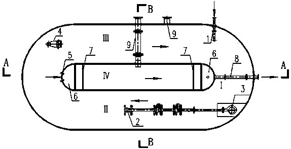
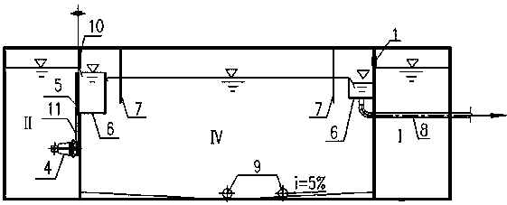
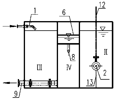
The invention discloses a jet membrane method internal circulation reactor. The reactor comprises an embedded inner shell and an embedded outer shell, wherein the upper end and the lower end of the inner shell are fixed on the upper end surface and the lower end surface of the outer shell respectively; the inner shell is a precipitation zone; the outer cavity of the inner shell is provided with abiological reaction zone; the outer biological reaction zone is provided with an anaerobic zone, an aerobic zone and an anoxic zone in sequence; a jet device and an ancillary submersible pump are arranged in the aerobic zone; a plug flow device is arranged at the starting end of the anoxic zone; a water outlet of the reactor is arranged at the tail end of the aerobic zone; a water inlet pipe is arranged at the starting end of the anaerobic zone; a shutter is arranged on the inner shell corresponding to the tail end of the aerobic zone, the inner shell is internally provided with a first overflow groove corresponding to the shutter; a first baffle is arranged outside the first overflow groove, the middle part of the bottom of the inner shell is provided with a mud pipe extending to the outer part of the outer shell; a second baffle and a second overflow groove are arranged on the tail end, in the water flow, of the inner shell in sequence, the second overflow groove is communicated witha water outlet pipe extending to the outer part of the outer shell. The invention also discloses a sewage treatment method by using the reactor. The reactorhas the advantages of simple structure, lowcost, convenient operation management and stable treatment effect.

Description

technical field [0001] The invention relates to a technology for treating domestic sewage in cities and towns, in particular to a jet membrane method internal circulation reactor and a sewage treatment method thereof. Background technique [0002] At present, my country's urban sewage treatment technology has problems such as complex equipment, high power consumption, large floor area, long construction period, and difficult operation, management and maintenance. [0003] Chinese patent CN100544808C discloses a method and device for a jet membrane-bioreactor, which pressurizes a part of the sludge mixture into the pipeline through a water pump, and entrains the surrounding air through the high-speed water flow formed by the nozzle of the jet. The mixing and cutting action dissolves a part of the air into the mixed liquid to form a gas-liquid jet flow, oxygenates the sludge mixed liquid through the diffusion air distribution plate and scours the membrane module; at the same t...

Claims


Application Information

Patent Timeline
IPC IPC(8): C02F3/30
CPCC02F3/30Y02W10/10
Inventor 邹玲珍段佩怡蒋蓓科
Owner HAINAN TIANHONG MUNICIPAL DESIGN CO LTD
Learn More