Package-stopping and package-distributing mechanism of vehicle-loading robot
A robot and installation-end technology, applied in the direction of conveyor, loading/unloading, transportation and packaging, etc., can solve the problems of limited material shifting position, increasing process, limited position of material bag shifting, etc., to achieve automatic blocking of material bags, improve Efficiency, ensure the effect of dialing in place
- Summary
- Abstract
- Description
- Claims
- Application Information
AI Technical Summary
Problems solved by technology
Method used
Image
Examples
Embodiment 1
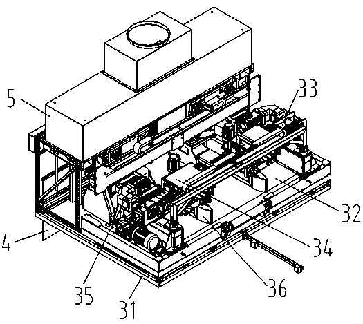
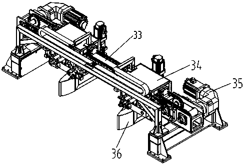
[0041] A kind of parking and subcontracting mechanism of the loading robot of the present embodiment, such as figure 1 and figure 2 As shown, it includes an outer frame 31 with a feed end and a discharge end, the inner bottom of the outer frame 31 is provided with a belt feeding mechanism 32 parallel to the feeding direction, and the top of the belt feeding mechanism 32 is vertically A guide rail 33 is provided in the feeding direction, and a mounting frame 34 is slidably sleeved on the guide rail 33, and one side of the guide rail 33 is provided with a frame driving device 35 for driving the mounting frame 34 to move linearly along the guide rail 33; the mounting frame 34 is provided with a paddle 36 parallel to the feeding direction; the top of the outer frame 31 is also provided with an organ cover dust collection device 5, and the discharge end of the outer frame 31 is provided with a dust curtain mechanism 4.
[0042] The bottom of the inner side of the outer frame 31 i...
Embodiment 2
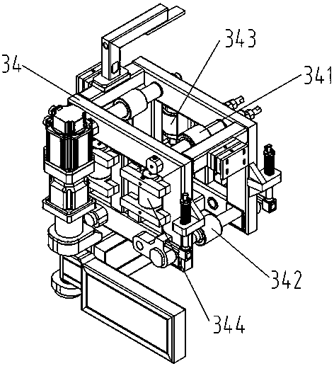
[0046] This embodiment is further optimized on the basis of embodiment 1, such as image 3 As shown, the bottom of the installation frame 34 is provided with a bottom surface tensioning guide wheel 342 which is slidingly connected with the bottom surface of the guide rail 33; Guide wheel 344.
[0047] The top of the installation frame 34 is provided with a top surface fixed guide wheel 341 that is slidably connected to the top surface of the guide rail 33 , and the front side of the installation frame 34 is provided with a front side fixed guide wheel 343 that is slidably connected with the front side of the guide rail 33 .
[0048] Front, back, top and bottom of the mounting frame 34 are respectively provided with guide wheels corresponding to the front side, the rear side, the top surface and the bottom surface of the guide rail. The top surface fixed guide wheel 341 is arranged on the top of the installation frame 34, and the top surface fixed guide wheel 341 is fixedly a...
Embodiment 3
[0052] This embodiment is further optimized on the basis of above-mentioned embodiment 1 or 2, such as Figure 4 As shown, the two ends of the axle of the bottom surface tensioning guide wheel 342 respectively pass through the installation frame 34 and extend to the outside of the installation frame 34 , and the two ends of the axle of the bottom surface tensioning guide wheel 342 are symmetrically provided with bottom surface tensioning devices 345 .
[0053] The two ends of the wheel shaft of the bottom surface tensioning guide wheel 342 are respectively installed through the front side and the rear side of the installation frame 34, that is, through holes are respectively provided at the corresponding positions on the front side and the rear side of the installation frame 34 for tensioning through the bottom surface. The two ends of the wheel shaft of guide wheel 342, and the aperture of through hole is greater than the diameter of the wheel shaft of bottom surface tension g...
PUM
 Abstract
Description
Claims
Application Information
 - R&D
- Intellectual Property
- Life Sciences
- Materials
- Tech Scout
- Unparalleled Data Quality
- Higher Quality Content
- 60% Fewer Hallucinations
Browse by: Latest US Patents, China's latest patents, Technical Efficacy Thesaurus, Application Domain, Technology Topic, Popular Technical Reports.
© 2025 PatSnap. All rights reserved.Legal|Privacy policy|Modern Slavery Act Transparency Statement|Sitemap|About US| Contact US: help@patsnap.com


