
Safety dustproof stirring device and implementation method thereof

A technology of a stirring device and a realization method, which is applied to a mixer with a rotary stirring device, accessories of a mixer, chemical instruments and methods, etc. Rapid and thorough mixing, improved shock resistance, and the effect of avoiding loosening

Inactive Publication Date: 2019-07-05
ANHUI UNIV OF SCI & TECH
View PDF10 Cites 0 Cited by
  • Summary
  • Abstract
  • Description
  • Claims
  • Application Information

AI Technical Summary

Problems solved by technology

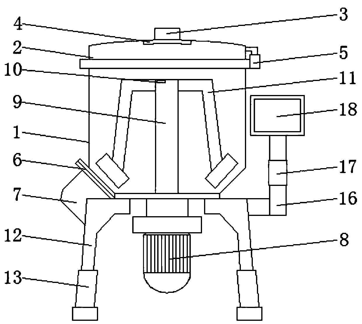
[0002] Engineering safety issues are very important in the construction industry. Engineering equipment is the first factor affecting construction safety, and mixing equipment is a commonly used mixing and stirring instrument in the engineering field. The mixing equipment is a shaft with blades in a cylinder or a tank. Rotating in the middle, mixing various raw materials to make it a mixture or a machine with a suitable consistency, but there are certain disadvantages in the use of the current mixer. First, a large amount of dust will be generated in the early stage of mixing, which will endanger people's health. And it is impossible to add water evenly, which is not conducive to people's use. Secondly, when the equipment fails, it cannot be found in time, resulting in excessive load on the motor, or even burning. In addition, the shock absorption capacity of the mixer is poor, which may easily lead to loose parts of the mixer. occur, therefore, we propose a safe dust-proof stirring device and its realization method

Method used


Image

  • Safety dustproof stirring device and implementation method thereof
  • Safety dustproof stirring device and implementation method thereof
  • Safety dustproof stirring device and implementation method thereof

Examples


Embodiment Construction

[0019] The following will clearly and completely describe the technical solutions in the embodiments of the present invention with reference to the accompanying drawings in the embodiments of the present invention. Obviously, the described embodiments are only some, not all, embodiments of the present invention.

[0020] In describing the present invention, it should be understood that the terms "upper", "lower", "front", "rear", "left", "right", "top", "bottom", "inner", " The orientation or positional relationship indicated by "outside", etc. is based on the orientation or positional relationship shown in the drawings, and is only for the convenience of describing the present invention and simplifying the description, rather than indicating or implying that the referred device or element must have a specific orientation, so as to Specific orientation configurations and operations, therefore, are not to be construed as limitations on the invention.

[0021] refer to Figure ...


PUM


Abstract

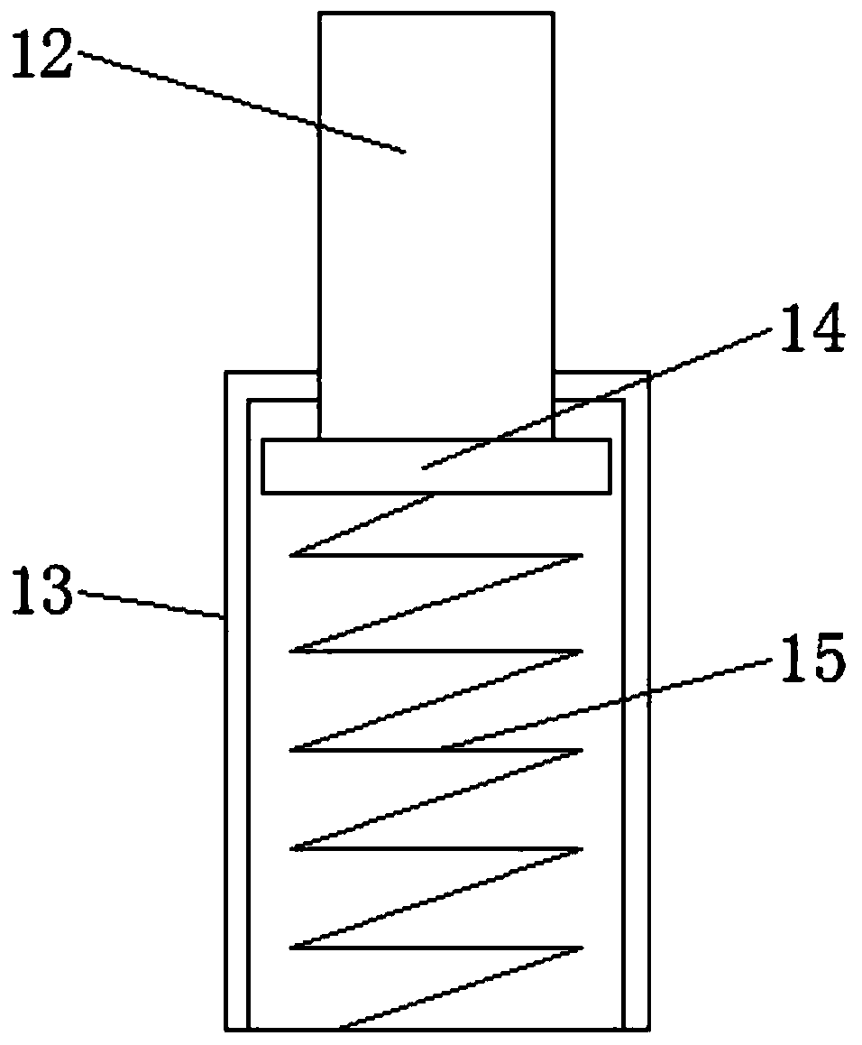
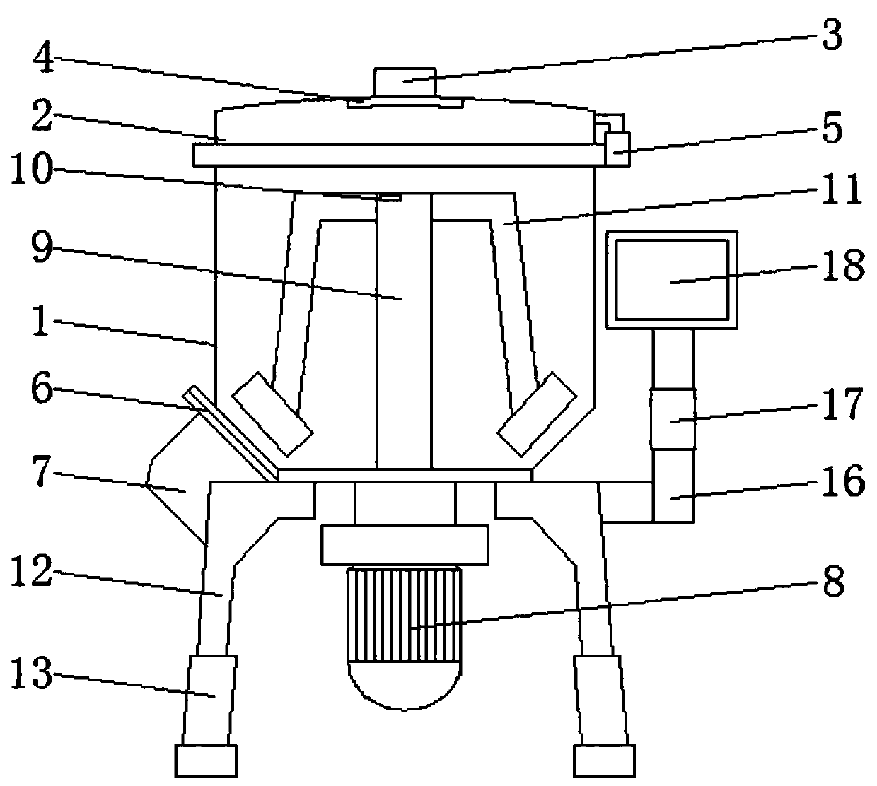
The invention discloses a safety dustproof stirring device and an implementation method thereof. The device comprises a stirring box body, the outer surface of the upper end of the stirring box body is provided with a dustproof cover, the center of the outer surface of the upper end of the dustproof cover is provided with a water inlet, a shower head is fixedly mounted at the center of the inner surface of the upper end of the dustproof cover, a hinge is arranged on one side of the upper end of the stirring box body, a discharge pulling plate is arranged on one side of the bottom endof the stirring box body,a driving motor is fixedly mounted at the center of the outer surface of the bottom end of the stirring box body, the outer surface of the upper end of the driving motor is provided with a rotating shaft, the inner surface of the upper end of the rotating shaft is fixedly provided with a rotation speed sensor, one side of the upper end of the rotating shaft is fixedly connected withstirring paddles, and supporting legsare fixedly mounted at the edge of the outer surface of the bottom end of the stirringbox body. The device has a simple structure, can prevent dust splashing in the stirring box body, can prevent the motor from being burnt, can improve the seismic resistance of a mixer, and is more practical.

Description

technical field [0001] The invention relates to the technical field of engineering safety equipment, in particular to a safety dustproof stirring device and a realization method thereof. Background technique [0002] Engineering safety issues are very important in the construction industry. Engineering equipment is the first factor affecting construction safety, and mixing equipment is a commonly used mixing and stirring instrument in the engineering field. Agitating equipment is a shaft with blades in a cylinder or tank. Rotating in the middle, mixing various raw materials to make it a mixture or a machine with a suitable consistency, but there are certain disadvantages in the use of the current mixer. First, a large amount of dust will be generated in the early stage of mixing, which will endanger people's health. And it is impossible to add water evenly, which is not conducive to people's use. Secondly, when the equipment fails, it cannot be found in time, resulting in ex...

Claims


Application Information

Patent Timeline
Patent Type & Authority Applications(China)
IPC IPC(8): B01F7/16B01F15/00B01F15/02
CPCB01F27/808B01F35/22B01F35/43B01F35/184B01F35/7179
Inventor 朱艳娜何刚乔国通
Owner ANHUI UNIV OF SCI & TECH
Learn More