Array arrangement type piezoelectric energy harvester applied to non-directional flow

An array arrangement, piezoelectric energy capture technology, applied in piezoelectric effect/electrostrictive or magnetostrictive motors, electrical components, generators/motors, etc. and other problems, to achieve the effect of simple incentive method, improved energy capture efficiency, and extended life.

Active Publication Date: 2019-06-28
HARBIN INST OF TECH
View PDF4 Cites 3 Cited by
  • Summary
  • Abstract
  • Description
  • Claims
  • Application Information

AI Technical Summary

Problems solved by technology

[0004] The purpose of the present invention is to provide an array-arranged piezoelectric energy harvester applied to non-directional flow, to solve the problem that most of the energy harvesters in the existing flow-induced vibration energy harvesting are fixed, although it can also achieve better Energy capture effect, but it cannot be applied to non-directional flow, and the application is limited

Method used


Image

  • Array arrangement type piezoelectric energy harvester applied to non-directional flow
  • Array arrangement type piezoelectric energy harvester applied to non-directional flow
  • Array arrangement type piezoelectric energy harvester applied to non-directional flow

Examples


Embodiment Construction

[0033] Preferred embodiments of the present invention will be described in detail below with reference to the accompanying drawings.

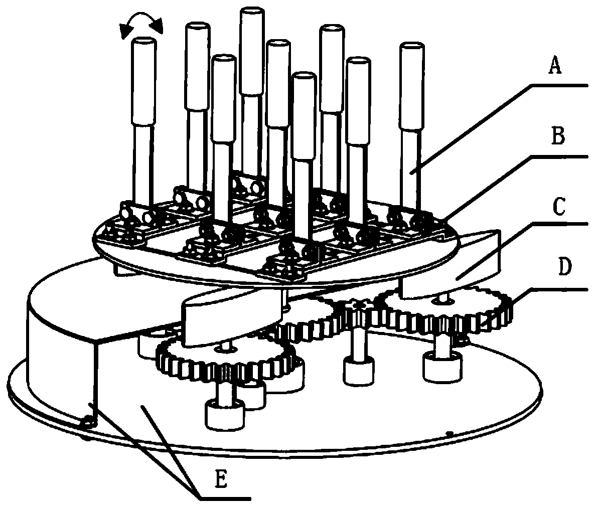
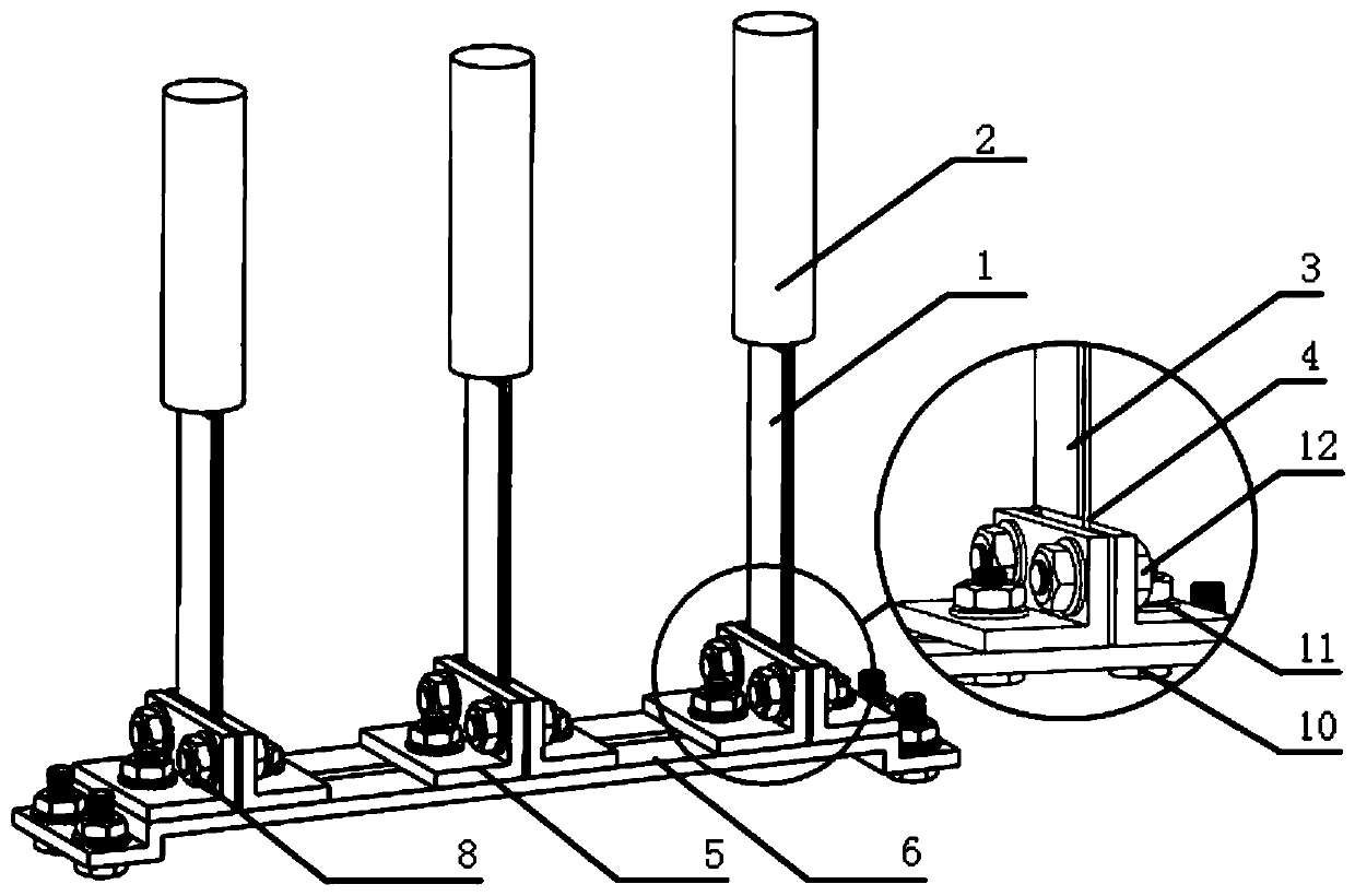
[0034] Such as Figure 1 to Figure 13 As shown, an array-arranged piezoelectric energy harvester applied to non-directional flow according to the present invention has an array form of 3*3, and specifically includes nine piezoelectric vibrators A, an array clamp mechanism B, and guide wings Mechanism C, gear transmission mechanism D and housing E; said gear transmission mechanism D is installed inside the housing E, and the gear transmission group D includes three driving gear shafts 38 and a driven gear shaft 40, and the guide wing mechanism C passes through the housing and The driving gear shaft 38 is connected, and the upper end of the driven gear shaft 40 passes through the shell E to connect with the array fixture mechanism B. The nine piezoelectric vibrators A are installed on the array fixture mechanism B, and the guide wings of the guid...


PUM


Abstract

The invention discloses an array arrangement type piezoelectric energy harvester applied to the non-directional flow, and belongs to the technical field of water flow and air flow induced vibration energy harvesting. The invention aims to solve the problems in the prior art that although most existing energy harvesters in the flow induced vibration energy harvesting field can realize the good energy harvesting effect, the energy harvesters are fixed and cannot be applied to the non-directional flow, thus being limited in application range. According to the technical scheme of the invention, the energy harvester comprises a plurality of piezoelectric vibrators, an array clamp mechanism, a guide wing mechanism, a gear transmission mechanism and a shell. The gear transmission mechanism is arranged in the shell. A gear transmission set comprises a plurality of driving gear shafts and a driven gear shaft. The guide wing mechanism penetrates through the shell to be connected with the drivinggear shafts. The upper end of the driven gear shaft penetrates out of the shell to be connected with the array clamp mechanism. The piezoelectric vibrators are arranged on the array clamp mechanism.The guide wings of the guide wing mechanism are located between the array clamp mechanism and the shell. The array arrangement type piezoelectric energy harvester is applied to the non-directional flow, wherein the motion states of the vibrators can be mutually coupled. The energy harvesting efficiency can be improved.

Description

technical field [0001] The invention relates to a piezoelectric energy harvester, in particular to an array-arranged piezoelectric energy harvester applied to non-directional flow, and belongs to the technical field of vibration energy harvesting caused by water flow and air flow. Background technique [0002] Flow-induced vibration energy harvesting is a technology that uses water or air flow to flow through non-streamlined objects, and the alternate shedding vortices will generate eddy-induced force to excite the vibration of the vibrator of the energy harvester, thereby generating electrical energy. [0003] The flow-induced vibration energy harvesting in the prior art is mostly applied to directional flow energy harvesters, and most of the energy harvesters are fixed. Although they can achieve better energy harvesting effects, they cannot be applied to non-directional flow. There are significant limitations. Contents of the invention [0004] The purpose of the presen...

Claims


Application Information

Patent Timeline
IPC IPC(8): H02N2/18
Inventor 单小彪王艺聪谢涛
Owner HARBIN INST OF TECH
Why Eureka
Try Eureka