
Electromagnetic brake motor

An electromagnetic brake and brake technology, applied in the direction of electric components, mechanical energy control, electrical components, etc., can solve problems such as troublesome installation, complicated installation, and difficult operation

Pending Publication Date: 2019-06-28
NANTONG XIONGYA ELECTROMECHANICAL MFG CO LTD
View PDF0 Cites 0 Cited by
  • Summary
  • Abstract
  • Description
  • Claims
  • Application Information

AI Technical Summary

Problems solved by technology

[0003] The electromagnetic brake of most motors is installed on the rear end cover of the motor, and a protective cover is installed outside. This method is complicated to install and the body is too long. There are also electromagnetic brakes installed inside the motor shell. The body structure is more compact, but the internal The installation of the electromagnetic brake is very troublesome, the internal space is small, it is difficult to operate, and the maintenance and replacement operations are cumbersome. If the friction part of the electromagnetic brake is stained with water or oil, etc., it will affect the braking effect.

Method used


Image

  • Electromagnetic brake motor
  • Electromagnetic brake motor
  • Electromagnetic brake motor

Examples


Embodiment Construction

[0015] The present invention will be described in further detail below in conjunction with the accompanying drawings.

[0016] In order to make the object, technical solution and advantages of the present invention clearer, the present invention will be further described in detail below in conjunction with the accompanying drawings and specific embodiments. The following examples can enable those skilled in the art to understand the present invention more comprehensively, but the present invention is not limited to the scope of the described examples.

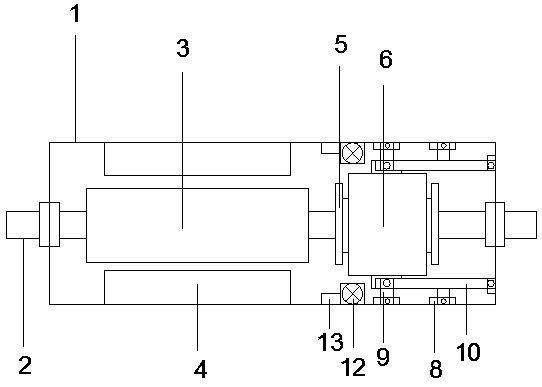
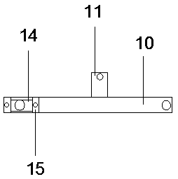
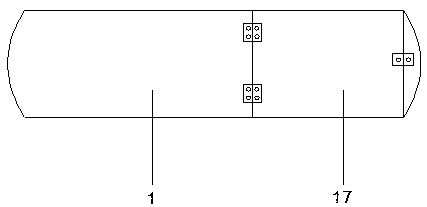
[0017] Such as Figure 1-Figure 4 As shown, this specific embodiment adopts the following technical scheme: it includes a motor housing 1, a rotating shaft 2, a rotor 3, a stator 4, a magnetic suspension bearing 5, a brake 6, a mounting block 7, a fixing block 8, a mounting plate 9, a connecting plate 10, Connecting strip 11, switch plate 17; the inner movable sleeve of the motor casing 1 is equipped with a rotating shaft 2, a...


PUM


Abstract

The invention discloses an electromagnetic brake motor, and relates to the technical field of motors. A rotating shaft is movably sleeved in a motor shell. The outer wall of the rotating shaft is fixedly sleeved with a rotor. The outer wall of the rotor is sleeved in a stator. The stator is fixedly arranged in an inner cavity of the motor shell. One side of the rotor is fixedly sleeved with a magnetic suspension bearing. A brake is arranged in the motor shell. Mounting blocks are respectively arranged at the top and the bottom of the brake. The brake is respectively connected with one ends ofmounting plates through the mounting blocks, while the other ends of the mounting plates are fixedly connected with fixing blocks respectively. Two fixing blocks are fixed in the inner cavity of the motor shell. The other end of a connecting plate is fixed to the fixing blocks, respectively. Two fixing blocks are arranged on the upper portion and the lower portion of the right side of the inner cavity of the motor shell respectively. A connecting strip is fixedly connected to the connecting plate, and the outer end of the connecting strip is fixed to the fixing blocks. The electromagnetic brake motor is compact and firm in structure, easy and convenient to install and convenient to maintain and replace.

Description

technical field [0001] The invention relates to the technical field of motors, in particular to an electromagnetic braking motor. Background technique [0002] The main function of the motor is to generate driving torque as a power source for electrical appliances or various machines. Electromagnetic brakes are mechanical parts that stop or slow down moving parts in machinery. The brake is mainly composed of a brake frame, brake parts and operating devices. Some brakes are also equipped with an automatic adjustment device for the clearance of the brake parts. Electromagnetic brake is an ideal automatic actuator in modern industry. It mainly plays the role of transmitting power and controlling motion in the mechanical transmission system. It has the advantages of compact structure, simple operation, sensitive response, reliable use, and easy remote control. . It is mainly matched with series motors. [0003] The electromagnetic brake of most motors is installed on the re...

Claims


Application Information

Patent Timeline
IPC IPC(8): H02K7/102
Inventor 范生详
Owner NANTONG XIONGYA ELECTROMECHANICAL MFG CO LTD
Learn More