
Mesh bearing test device and method

A test device and mesh technology, applied in the direction of measuring force components, etc., can solve the problems of inability to measure directly, low data processing efficiency, and large error in results, etc., and achieve the effects of simple structure, guaranteed data, and low manufacturing cost

Pending Publication Date: 2019-06-28
TIANJIN RES INST FOR WATER TRANSPORT ENG M O T
View PDF0 Cites 2 Cited by
  • Summary
  • Abstract
  • Description
  • Claims
  • Application Information

AI Technical Summary

Problems solved by technology

[0002] Restricted by the measurement method in the existing technology, it is seldom to measure the force of a single mesh, but to measure the force of the whole cage, and the measurement of the whole cage, because the cage will be under the action of waves The reciprocating motion cannot be directly measured, and the method of indirect measurement is usually used, that is, the overall force of the cage is solved by measuring the tension of the spring that constrains the cage, and then the force of the mesh is calculated, resulting in low data processing efficiency and results. large error
At the same time, in the process of measuring the overall force of the cage, the tension sensor can only measure the force along the direction of the spring, and the change of the tension angle cannot be obtained due to the change of the position of the cage, which leads to deducing the force of the cage according to the force of the spring There will be errors when calculating the force on the mesh, which will further lead to greater errors

Method used


Image

  • Mesh bearing test device and method
  • Mesh bearing test device and method
  • Mesh bearing test device and method

Examples


Embodiment

[0045] 1.1 Test device for mesh stress

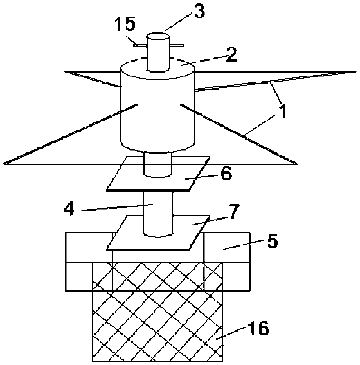
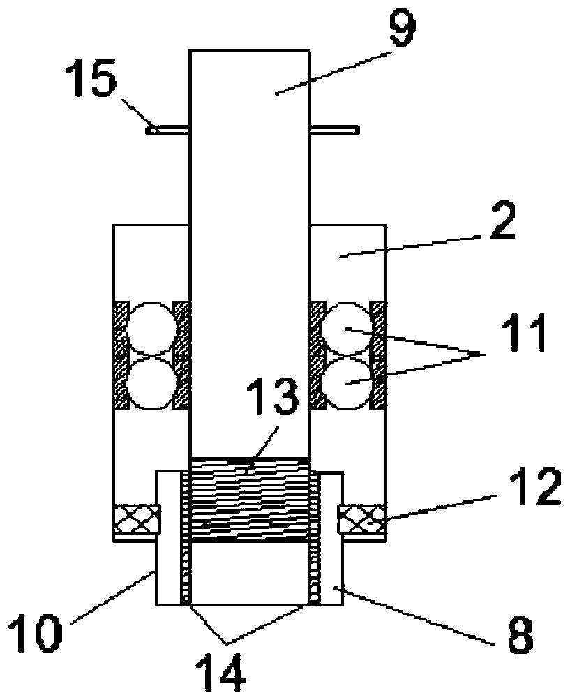
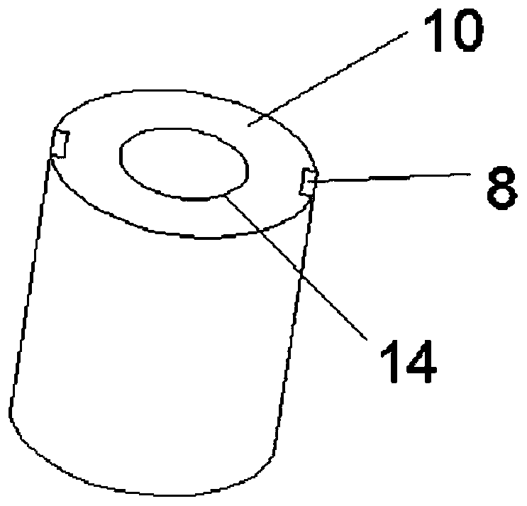
[0046] Such as Figures 1 to 3 Shown, a kind of testing device of mesh force, comprises bracket 1, sleeve 2, lifting device 3, three-component force sensor 4 and mesh fixing frame 5;

[0047] The bracket 1 is fixed on the outer wall of the sleeve 2 to support the whole device. The bracket 1 can be a lap arm symmetrically arranged on both sides of the sleeve 2 and can be lapped on the side wall of the test tank;

[0048] The sleeve 2 is provided with a through hole along its axial direction, and the sleeve 2 is sleeved on the outside of the lifting device 3; the lifting device 3 includes a screw rod 9, a lifting rod 10 and a ball bearing 11; the upper end of the screw rod 9 is provided with a rotating handle 15, and the screw rod The lower end of 9 is inserted in the through hole through the top of sleeve 2, and the inner side wall of sleeve 2 and the outer side wall of screw rod 9 are rotationally connected by ball bearing 11; the uppe...


PUM


Abstract

The invention provides a mesh bearing test device which comprises a support, a sleeve, an elevating device, a three component force sensor and a mesh mount. The support is fixed to the outer sidewallof the sleeve; the sleeve sleeves the elevating device; the elevating end of the elevating device is connected to one end of the three component force sensor via a first connecting plate; and the other end of the three component force sensor is connected with mesh mount via a second connecting plate. The mesh bearing test device is simple in structure and convenient to operation, bearing conditions in three directions x, y and z within an experimental water area of a mesh can be measured directly, measuring and calculating errors are reduced greatly, the experiment efficiency is improved and the test cost is reduced.

Description

technical field [0001] The invention belongs to the technical field of hydrodynamic parameter measurement, and in particular relates to a test device and method for the stress of a mesh sheet. Background technique [0002] Restricted by the measurement method in the existing technology, it is seldom to measure the force of a single mesh, but to measure the force of the whole cage, and the measurement of the whole cage, because the cage will be under the action of waves The reciprocating motion cannot be directly measured, and the method of indirect measurement is usually used, that is, the overall force of the cage is solved by measuring the tension of the spring that constrains the cage, and then the force of the mesh is calculated, resulting in low data processing efficiency and results. The error is large. At the same time, in the process of measuring the overall force of the cage, the tension sensor can only measure the force along the direction of the spring, and the c...

Claims


Application Information

Patent Timeline
IPC IPC(8): G01L5/16
Inventor 金瑞佳陈松贵戈龙仔耿宝磊张维马隽熊岩栾英妮赵旭张华庆
Owner TIANJIN RES INST FOR WATER TRANSPORT ENG M O T
Learn More