
Drilling machine for coal mine underground rail

A drilling machine, track technology, applied in the direction of boring/drilling, drilling/drilling equipment, components of boring machine/drilling machine, etc., can solve the problems of high labor intensity, high cost, increased volume, weight and cost, etc. , to achieve the effect of improving work efficiency, strong applicability and high cost performance

Pending Publication Date: 2019-06-28
CHANGZHOU DEV & MFR CENT
View PDF0 Cites 0 Cited by
  • Summary
  • Abstract
  • Description
  • Claims
  • Application Information

AI Technical Summary

Problems solved by technology

[0002] Due to the needs of installation and use, underground rails in coal mines often need to be drilled, reamed and chamfered. Since the equipment used in underground coal mines must meet the explosion-proof requirements, electric rail drilling machines and internal combustion engine rail drilling machines are widely used on the ground. Because the electrical explosion-proof of the motor and the explosion-proof of the intake and exhaust of the internal combustion engine do not meet the requirements, the machine cannot be used in the underground environment of coal mines. If explosion-proof treatment is required, the volume, weight and cost will increase sharply, and the portability and lightness of the orbital drilling machine will be lost, and the cost will be relatively high
[0003] At present, manual hydraulic punching machines are basically used in underground coal mine drilling operations. Although they can meet the requirements of portable, portable and explosion-proof working conditions, using manual hydraulic punching machines for hydraulic pressing and extrusion track punching is labor-intensive and efficient. very low

Method used


Image

  • Drilling machine for coal mine underground rail
  • Drilling machine for coal mine underground rail
  • Drilling machine for coal mine underground rail

Examples


Embodiment 1)

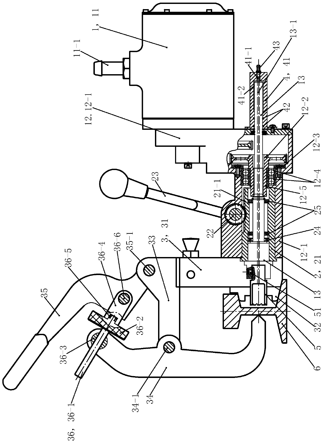
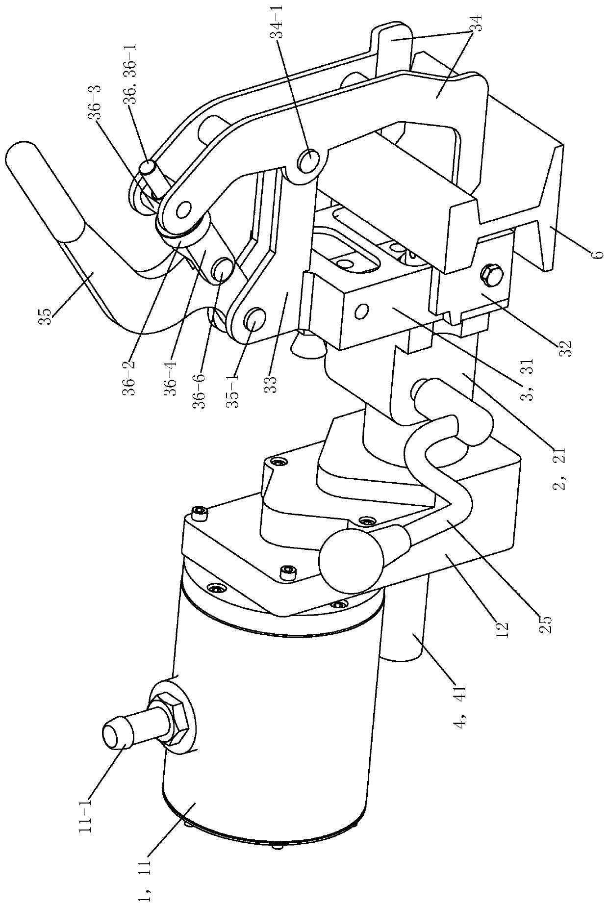
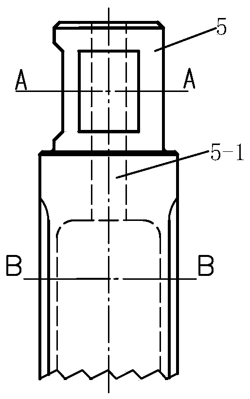
[0031] See figure 1 and figure 2 , The coal mine underground track drilling machine of this embodiment is mainly composed of a drive assembly 1, a feed assembly 2, a clamp assembly 3, a bushing assembly 4 and a drill bit 5.

[0032] The drive assembly 1 includes an air motor 11 , a reducer 12 and a transmission shaft 13 .

[0033] The air motor 11 is a commercially available product. The air motor 11 has an air inlet nozzle 11-1 and an output shaft. The air motor 11 can be a gear-type, vane-type or turbine-type air motor. The mouth 11-1 is connected to the existing compressed air in the coal mine as a power source through an air pipe to provide driving force. Reducer 12 has housing 12-1, input shaft and final stage gear 12-2, and reducer 12 is the reducer that is provided with two-stage reduction gear, and housing 12-1 is a hollow housing, and housing 12-1 It has integrally connected right and left parts, the input shaft and the two-stage reduction gear including the final...


PUM


Abstract

The invention provides a drilling machine for a coal mine underground rail. The machine comprises a drill bit, a driving assembly, a feeding assembly, a clamping assembly and a shaft sleeve assembly;the driving assembly comprises a pneumatic motor, a speed reducer and a transmission shaft, wherein the speed reducer and the transmission shaft are in transmission connection with the pneumatic motor, and the drill bit is fixedly connected with the transmission shaft; the feeding assembly comprises a feeding transmission supporting piece, a feeding gear shaft and a feeding handle, wherein the feeding transmission supporting piece is arranged in a speed reducer shell, the feeding gear shaft is arranged on the shell and is in meshed transmission with the feeding transmission supporting piece, and the feeding handle is fixedly connected with the feeding gear shaft; the clamping assembly comprises a clamping frame, a positioning clamping plate, two connecting arms, two clamping arms, a clamping handle, and an adjustable connecting piece; and the shaft sleeve assembly comprises a sleeve body, a sealing ring and a cooling liquid connector. The machine is portable and light, meets the coal mine underground explosion-preventing requirements, is simple, time-saving and labor-saving in operation during use, and is capable of improving the construction efficiency compared with similar devices in the prior art.

Description

technical field [0001] The invention relates to track drilling equipment, in particular to an underground track drilling machine for coal mines. Background technique [0002] Due to the needs of installation and use, underground rails in coal mines often need to be drilled, reamed and chamfered. Since the equipment used in underground coal mines must meet the explosion-proof requirements, electric rail drilling machines and internal combustion engine rail drilling machines are widely used on the ground. Because the electrical explosion-proof of the motor and the explosion-proof of the intake and exhaust of the internal combustion engine do not meet the requirements, the machine cannot be used in the underground environment of coal mines. If explosion-proof treatment is required, the volume, weight and cost will increase sharply, and the portability and lightness of the orbital drilling machine will be lost, and the cost will be relatively high. [0003] At present, manual h...

Claims


Application Information

Patent Timeline
IPC IPC(8): B23B41/00B23B47/00
Inventor 张弘史发慧张莹莹胡志华
Owner CHANGZHOU DEV & MFR CENT
Learn More