
Laser Differential Confocal Precision Measurement Method of Spherical Inertial Elements with Gap

A differential confocal and fit gap technology, applied in the direction of measuring devices, optical devices, instruments, etc., can solve the problem of difficult accurate control of the fit gap of the ball bowl and spherical crown of inertial devices, so as to improve the accuracy and work reliability , Strong suppression characteristics, high focus precision effect

Active Publication Date: 2020-08-11
BEIJING INSTITUTE OF TECHNOLOGYGY +1
View PDF15 Cites 0 Cited by
  • Summary
  • Abstract
  • Description
  • Claims
  • Application Information

AI Technical Summary

Problems solved by technology

[0005] Aiming at the problem that it is difficult to accurately control the matching clearance of the ball bowl and spherical crown of the inertial device, the present invention proposes a laser differential confocal high-precision method for the matching clearance of the spherical inertial element

Method used


Image

  • Laser Differential Confocal Precision Measurement Method of Spherical Inertial Elements with Gap
  • Laser Differential Confocal Precision Measurement Method of Spherical Inertial Elements with Gap
  • Laser Differential Confocal Precision Measurement Method of Spherical Inertial Elements with Gap

Examples


Embodiment 1

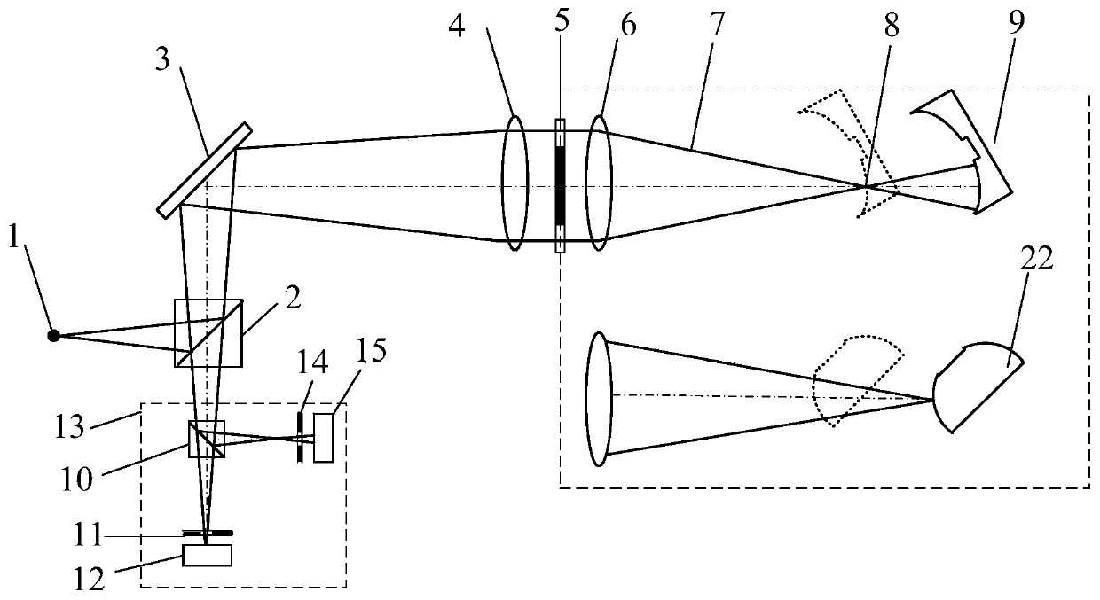
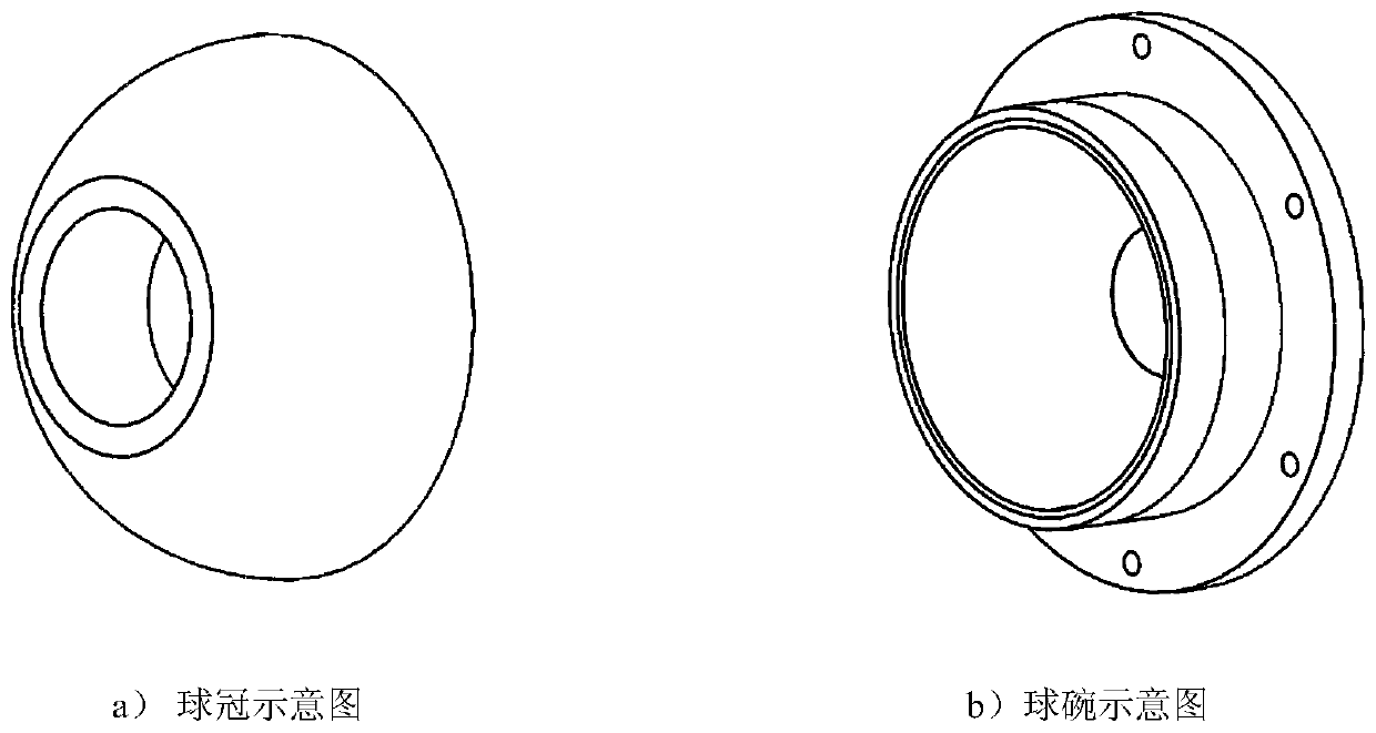
[0045] This embodiment is a schematic diagram of a ball bowl for a hemispherical dynamic pressure air bearing. image 3 -b) as an example to measure. Such as Figure 5 shown, based on figure 1 In the laser differential confocal inertial element curvature radius measurement method shown, the measurement steps are:

[0046] 1) Start the measurement software in the main control computer 18, turn on the laser 23, and the light emitted by the laser 23 is transmitted through the optical fiber 24 to form a point light source 1. The light emitted by the point light source 1 passes through the dichroic prism 2, the beam splitter 3, the collimating lens 4, the annular pupil 5, and the converging lens 6 to form a measuring beam;

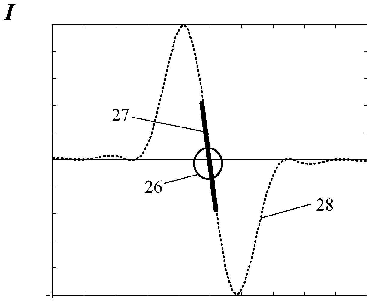
[0047] 2) The ball bowl is fixed on the five-dimensional adjustment frame 25, the measuring beam is irradiated on the surface of the ball bowl to be measured, and the light reflected from the surface of the ball bowl passes through the converging lens 6 and ...

Embodiment 2

[0084] This embodiment is a schematic diagram of a spherical crown for a hemispherical dynamic pressure air bearing, as shown in image 3 -a) as an example to measure. Such as Figure 6 shown, based on figure 1 In the laser differential confocal inertial element curvature radius measurement method shown, the measurement steps are:

[0085] All the other steps are the same as the testing steps of the ball bowl in embodiment 1.

[0086] After repeated tests, the average value of the radius of curvature of the spherical crown was measured

[0087] Then the fit gap between the ball crown and the ball bowl is as follows: Figure 4 Shown:

[0088]

[0089] Through repeated experiments and calculations, the clearance of the hemispherical dynamic pressure air bearing is 2.5 μm. The method can be used for random inspection and measurement of the curvature radii of various spherical crowns and spherical bowls on the production line of spherical parts of inertial devices, ther...


PUM


Abstract

The invention relates to a spherical inertial element tolerance clearance laser differential confocal high-precision method, and belongs to the technical field of optical precision measurement. The method comprise steps of separately measuring the curvature radiuses of a spherical bowl and a spherical crown by using anti-scattering laser differential confocal curvature radius measurement method; then measuring a radius difference between the spherical bowl and the spherical crown by using a differential confocal curvature radius measurement system in order to control the tolerance clearance ofthe spherical surface of the spherical inertia element. For the first time, the method applies the differential confocal technology with good anti-scattering characteristics to the accurate curvatureradius measurement of a spherical inertial spherical element with a notched surface and not fully polished, realizes the accurate control of the tolerance clearance between the spherical crown and the spherical bowl of an inertial device, uses the differential confocal technology in the measurement field of the radius of curvature of the spherical inertial element, and has a high value in the actual engineering to improve the accuracy and reliability of a ball bearing.

Description

technical field [0001] The invention relates to a laser differential confocal precision measurement method for a spherical inertial element with a gap, and belongs to the technical field of precise measurement of spherical element parameters of a spherical inertial device. Background technique [0002] With the continuous advancement of inertial technology, spherical inertial devices are widely used in aerospace, weapons, engineering surveying and other technical fields, such as spherical caps and bowls of air-floating spherical dynamic pressure gyroscopes, aeroengine universal rods, and spherical bearings. , Hydraulic transmission universal rod, etc. Fitting clearance is one of the key parameters to determine the accuracy and reliability of spherical inertial devices, but the mechanical structure of spherical inertial devices often has gaps and incomplete polishing on the surface due to the application, which brings difficulties to the high-precision measurement of the radi...

Claims


Application Information

Patent Timeline
Patent Type & Authority Patents(China)
IPC IPC(8): G01B11/14
Inventor 赵维谦姚竹贤许鑫邱丽荣王允
Owner BEIJING INSTITUTE OF TECHNOLOGYGY
Learn More