Closestool waterway switching control system and closestool

A waterway switching and control system technology, which is applied in flushing toilets, water supply devices, flushing equipment with water tanks, etc., can solve the problems of being unable to meet the diverse switching needs of toilet waterways, unfavorable product promotion, and increasing product costs. Simple structure, strong practicability, and the effect of improving scouring ability

Pending Publication Date: 2019-06-25
COMPAS XIAMEN PLUMBING TECH
View PDF0 Cites 1 Cited by
  • Summary
  • Abstract
  • Description
  • Claims
  • Application Information

AI Technical Summary

Problems solved by technology

[0002] The existing toilet waterway switching control system includes a buoy and a switching member linked with the buoy. The buoy can float up or down with the water level of the water tank, and then drive the switching member to open the first waterway or the second waterway. Waterway, in which the buoy is only switched once during the process of falling with the water level, for example: switching from opening the first waterway to opening the second waterway, however, when it is necessary to switch from opening the second waterway to opening the first waterway again, the buoy is required Floating drives the switching part to reset to realize the opening of the first waterway again. Therefore, the buoy in this scheme can only switch once when the water level of the water tank falls, which cannot meet the diverse switching needs of the toilet waterway. And other electronic control mechanisms, according to the preset program settings to achieve diversified switching, but the cost of the motor is high, which greatly increases the product cost, and it is necessary to connect a power line or battery to supply power to the electronic control mechanism, which is obviously not conducive to the development of the product. to promote

Method used


Image

  • Closestool waterway switching control system and closestool
  • Closestool waterway switching control system and closestool
  • Closestool waterway switching control system and closestool

Examples


Embodiment Construction

[0034] In order to make the technical problems, technical solutions and beneficial effects to be solved by the present invention clearer and clearer, the present invention will be further described in detail below in conjunction with the accompanying drawings and embodiments. It should be understood that the specific embodiments described here are only used to explain the present invention, not to limit the present invention.

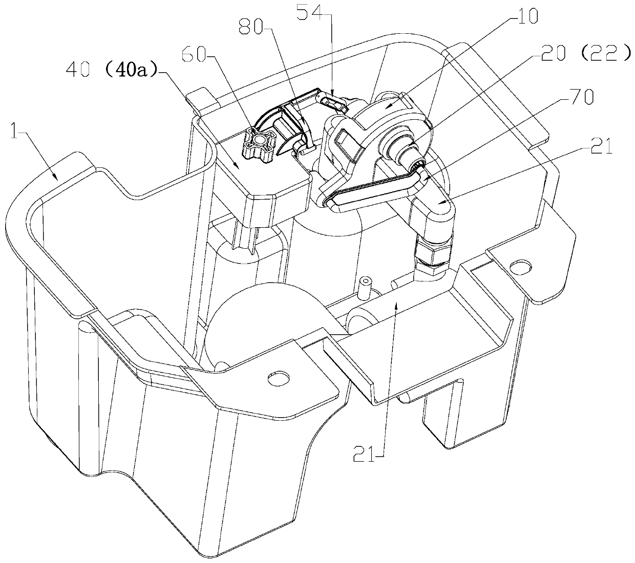
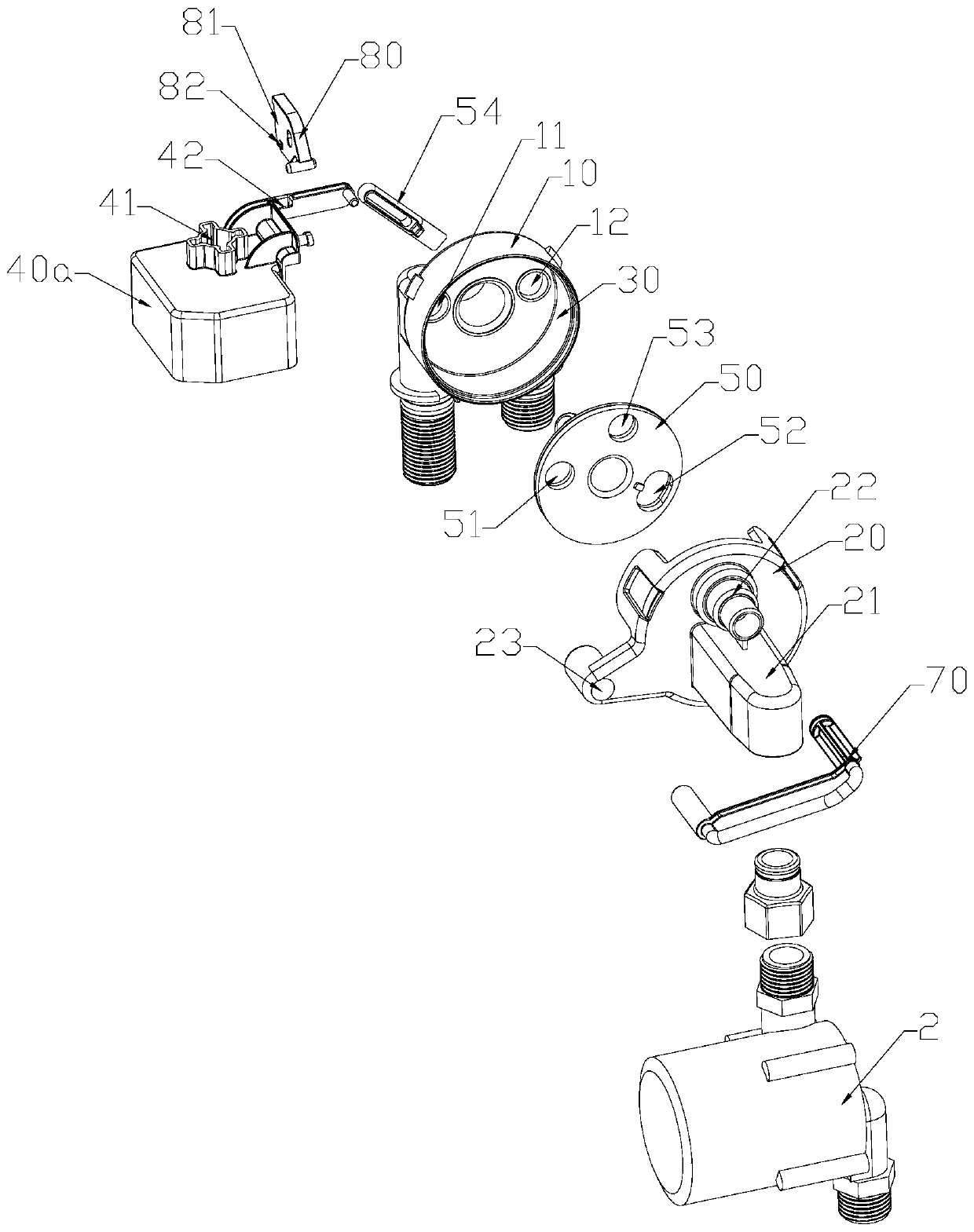
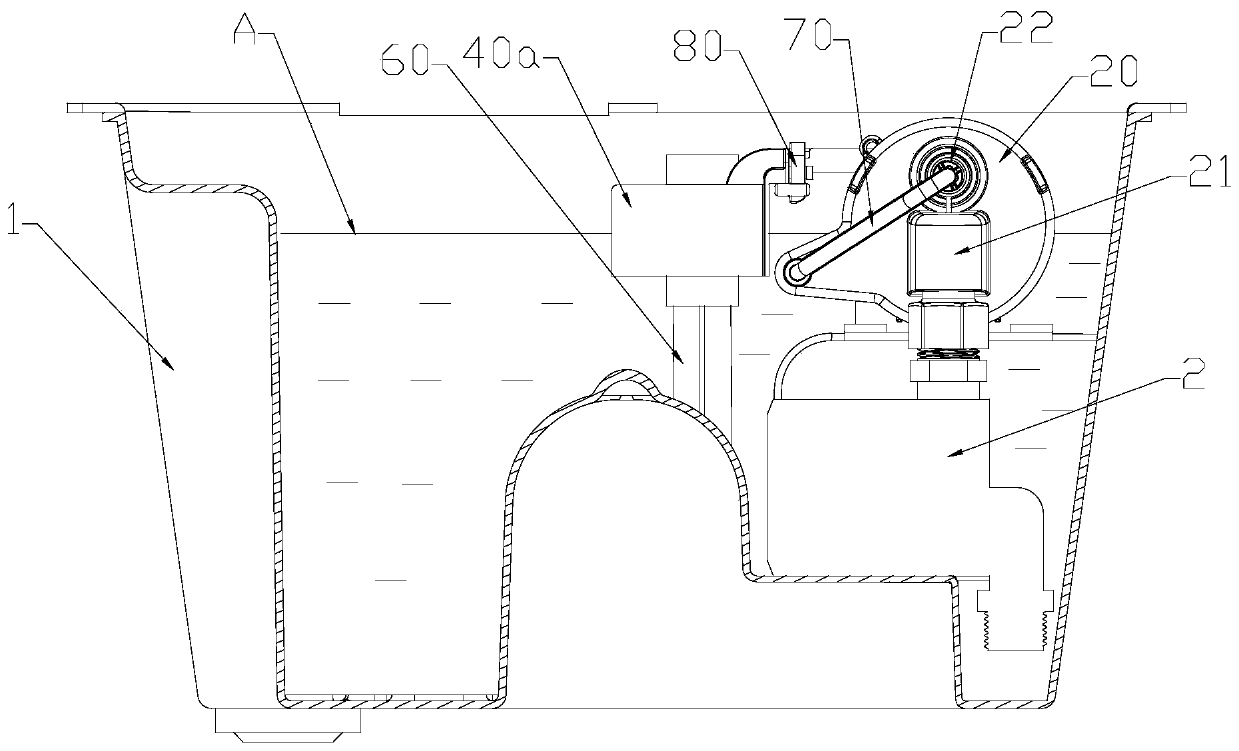
[0035] Such as Figure 1 to Figure 15As shown, a toilet waterway switching control system, the toilet includes a first waterway, a second waterway, a switching mechanism and a switch valve 2, the switching mechanism includes a first waterway 11, a second waterway 12 and a pressure waterway 21, the first waterway A waterway 11 communicates with the first waterway, the second waterway 12 communicates with the second waterway, and the on-off of the pressure waterway 21 is controlled by the switch valve 2, and the switching mechanism also includes a buoy T...


PUM


Abstract

The invention discloses a closestool waterway switching control system and a closestool. A switching mechanism comprises a first waterway, a second waterway and a pressure water channel, wherein the pressure water channel pumps water to a water tank of the closestool through a pump device, the switching mechanism further comprises a buoy assembly and a switching piece, in an initial state, the water level of the water tank is at a first water level, the switching piece is communicated with the pressure water channel and the first waterway, and when the water level falls to a second water level, the buoy assembly falls to a second position, thus the switching piece is driven to enable the pressure water channel to be communicated with the first waterway, when the water level falls to a third water level, the buoy assembly falls to a third position, and thus the switching piece is driven to make the pressure water channel communicated with the first waterway again. Reciprocating switching of the first waterway and the second waterway can be achieved in the process that a buoy falls with water level falling of the water tank, thus the flushing capability of the closestool is improved,multiple times of switching of the waterways in the buoy falling process are achieved through a pure mechanical structure, the product cost can be reduced, and the closestool waterway switching control system is simple in structure and high in practicability.

Description

technical field [0001] The invention relates to a toilet waterway switching control system and a toilet. Background technique [0002] The existing toilet waterway switching control system includes a buoy and a switching member linked with the buoy. The buoy can float up or down with the water level of the water tank, and then drive the switching member to open the first waterway or the second waterway. Waterway, in which the buoy is only switched once during the process of falling with the water level, for example: switching from opening the first waterway to opening the second waterway, however, when it is necessary to switch from opening the second waterway to opening the first waterway again, the buoy is required Floating drives the switching part to reset to realize the opening of the first waterway again. Therefore, the buoy in this scheme can only switch once when the water level of the water tank falls, which cannot meet the diverse switching needs of the toilet wate...

Claims


Application Information

Patent Timeline
IPC IPC(8): E03D1/33E03D1/34E03D1/32E03D1/36E03D11/02
Inventor 陈名琨张逢钿
Owner COMPAS XIAMEN PLUMBING TECH
Why Eureka
Try Eureka