Evaporation device

A technology of evaporation and evaporation source, which is applied in vacuum evaporation plating, sputtering plating, ion implantation plating, etc. It can solve the problems of high mechanical structure precision, small size, damage to the smooth surface of the inner wall, etc.

Pending Publication Date: 2019-06-25
HEFEI XINSHENG OPTOELECTRONICS TECH CO LTD +1
View PDF4 Cites 1 Cited by
  • Summary
  • Abstract
  • Description
  • Claims
  • Application Information

AI Technical Summary

Problems solved by technology

However, the efficiency of this method to increase the temperature of the evaporation nozzle is very low, and it takes a long time to heat up, so it often takes several hours to solve the plugging phenomenon with this method, which takes a long time
[0005] Another solution is to dredge the evaporation nozzle through the mechanical struct

Method used


Image

  • Evaporation device
  • Evaporation device
  • Evaporation device

Examples


Embodiment Construction

[0026] Exemplary embodiments of the present invention are described in detail below. The exemplary embodiments described below and illustrated in the accompanying drawings are intended to teach the principles of the invention and enable those skilled in the art to implement and use the invention in a number of different environments and for a number of different applications.

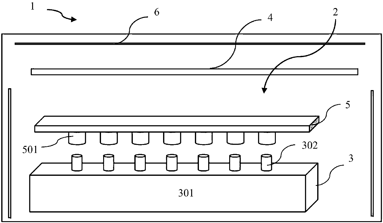
[0027] figure 1 An embodiment of a vapor deposition device 1 according to the invention is shown. As can be seen from the figure, the evaporation device 1 includes an evaporation source 3, the evaporation source 3 has a housing and a plurality of evaporation nozzles 302 arranged on the top of the housing; and an electromagnetic induction heater, which is used for The evaporation nozzle is heated, wherein the electromagnetic induction heater is arranged so that the relative distance between it and the evaporation nozzle 302 can be adjusted. This electromagnetic induction heater adopts the principle of e...


PUM


Abstract

The invention provides an evaporation device, which comprises an evaporating source and an electromagnetic induction heater. The evaporating source is provided with a shell and a plurality of evaporating nozzles arranged at the top of the shell; and the electromagnetic induction heater is used for heating the evaporating nozzles, and arranged to have the adjustable distance relative to the evaporating nozzles. By adopting the electromagnetic induction heater, vortexes are generated in the evaporating nozzles and quickly heated, blocked materials are evaporated, and the phenomenon that the evaporating nozzles are blocked in the evaporating process of the organic materials can be conveniently avoided.

Description

technical field [0001] The present invention generally relates to the field of evaporation, in particular to an evaporation device. Background technique [0002] At present, the organic evaporation source used in the evaporation of large-sized organic light-emitting diodes (OLEDs) is a line source. Generally, the configuration of the evaporation source is roughly the shell with the evaporation nozzle, the inner crucible, and the materials in the crucible from the outside to the inside. [0003] During the evaporation process, the material in the crucible is evaporated at high temperature, comes out from the gap at the top of the crucible, and then comes out through the evaporation nozzle, and then evaporated onto the glass substrate. Once the hole is blocked, the organic material will block the entire evaporation nozzle, so that the material cannot be completely evaporated. [0004] The traditional solution is to install a heating wire near the evaporation nozzle, and incr...

Claims


Application Information

Patent Timeline
IPC IPC(8): C23C14/26
Inventor 姚固邹清华段廷原曾苏伟王玉李慧慧栾梦雨王欣竹胡友元吴新风李菲熊先江
Owner HEFEI XINSHENG OPTOELECTRONICS TECH CO LTD
Why Eureka
Try Eureka