Rotor, motor, water pump and vehicle
A rotor and rotor core technology, applied in the field of vehicles, can solve problems such as inability to give accurate magnetization positioning and insufficient magnetization, and achieve the effects of eliminating the need for fasteners, improving accuracy, and improving production efficiency
- Summary
- Abstract
- Description
- Claims
- Application Information
AI Technical Summary
Problems solved by technology
Method used
Image
Examples
Embodiment 1
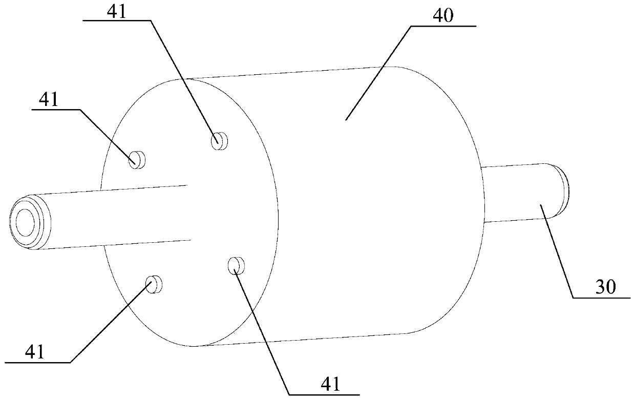
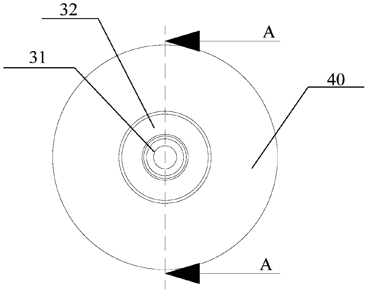
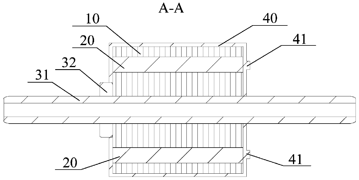
[0089] Specifically, the positioning structure 70 includes a positioning portion 71 for directly or indirectly positioning the position of the magnetic steel 20 .
[0090] The positioning structure 70 includes a positioning portion 71 , and using the positioning portion 71 to locate the positions of the plurality of magnets 20 is beneficial to improving the positioning speed of the positions of the magnets 20 , thereby improving the magnetization efficiency. Wherein, the number of positioning parts 71 can be equal to or not equal to the number of magnets 20, and can be used to directly locate the position of magnets 20, and can also be used to indirectly locate the position of magnets 20 . For example: some positioning parts 71 directly correspond to the center position of the magnet 20 and are used to directly locate the position of the magnet 20 , and some positioning parts 71 are located on both sides of the magnet 20 and are used to indirectly locate the position of the ma...
Embodiment 2
[0099] The difference from Embodiment 1 is that the number of positioning parts 71 is equal to the number of magnets 20 , and multiple positioning parts 71 cooperate to indirectly locate the positions of multiple magnets 20 .
[0100] Furthermore, a plurality of magnetic steels 20 are evenly distributed along the circumferential direction of the rotating shaft, and the positioning part 71 is located at the center between two adjacent strip structures, as Figure 6 shown.
[0101] The positioning part 71 is located in the center between two adjacent strip structures, and the middle position of the two positioning parts 71 is a magnetic steel 20, such as Figure 6 shown.
Embodiment 3
[0103] The difference from Embodiment 1 is that the line connecting the center of the strip structure and the center of the end face of the rotor passes through the positioning part 71, such as Figure 7 shown.
[0104] The connecting line between the center of the strip structure and the center of the end face of the rotor passes through the positioning part 71, then the connecting line between the center of the positioning part 71 and the center of the end face of the rotor must pass through the center position of the magnetic steel 20, and the magnetizing head faces the positioning part 71, and it is also exactly The center position of the magnet steel 20 can be accurately magnetized to the magnet steel 20 .
PUM
 Abstract
Description
Claims
Application Information
 - R&D Engineer
- R&D Manager
- IP Professional
- Industry Leading Data Capabilities
- Powerful AI technology
- Patent DNA Extraction
Browse by: Latest US Patents, China's latest patents, Technical Efficacy Thesaurus, Application Domain, Technology Topic, Popular Technical Reports.
© 2024 PatSnap. All rights reserved.Legal|Privacy policy|Modern Slavery Act Transparency Statement|Sitemap|About US| Contact US: help@patsnap.com


