


Quick Research
Generate reliable direction feasibility study reports for your R&D in just a few steps.

Technical Q&A
Discover and master advanced knowledge NOW. Basics, ideas, possibilities, all at once.

Find Solutions
As an expert in R&D theories, this can generate solutions to your technical problems instantly.

Evaluate Feasibility
Analyze your overall solution with one click, know your potential R&D risks in advance.

Monitor Landscape
Get weekly tech updates, stay abreast of the latest tech innovations and key insights.
Asymmetric Microdisk Cavity Edge-Emitting Semiconductor Laser Array
A laser array and laser technology, which is applied to semiconductor laser devices, laser devices, structures of optical resonators, etc., to achieve the effects of good heat dissipation, consistent light output directions, and easy output coupling
- Summary
- Abstract
- Description
- Claims
- Application Information
AI Technical Summary
Problems solved by technology
Method used
Image

Examples
Embodiment 1
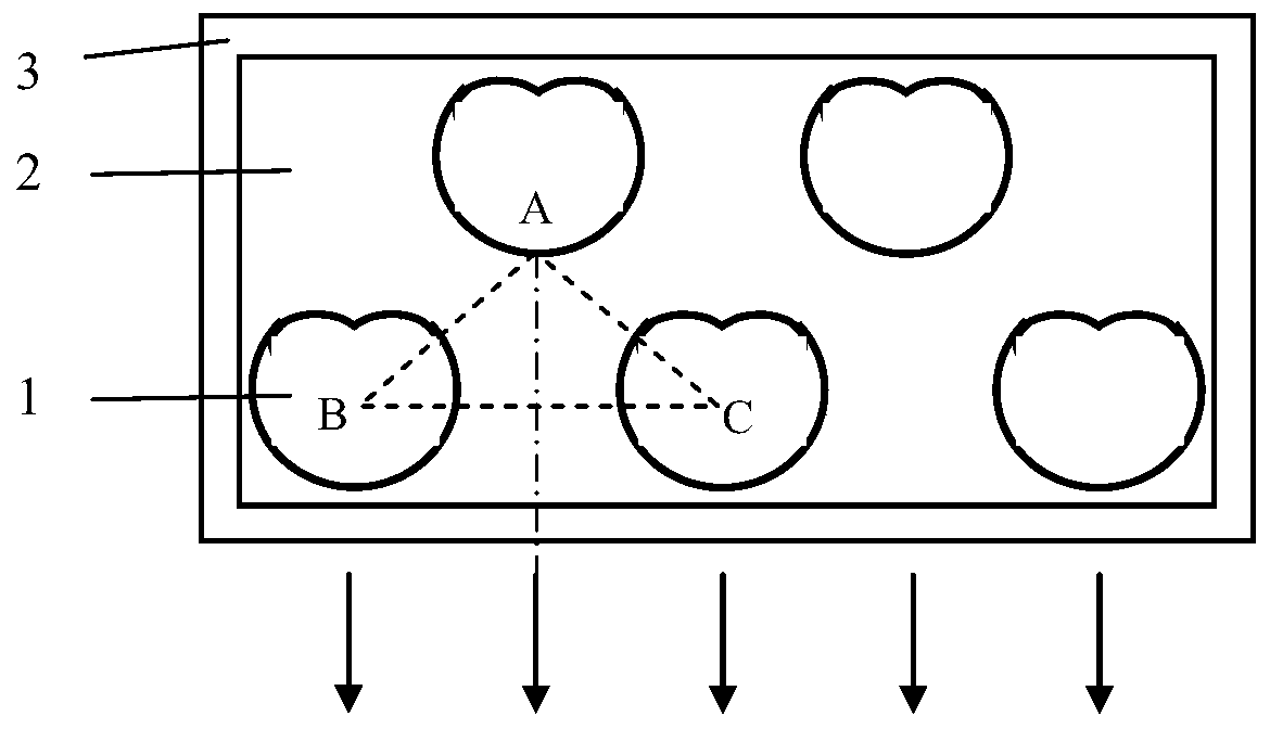
[0014] The number of laser tubes in the front row of laser lines and the back row of laser lines are both 4, such as figure 2 As shown, the asymmetric microdisk cavity is a snail-shaped microdisk cavity, and the snail-shaped polar coordinate equation of the snail-shaped microdisk cavity is ρ(θ)=ρ 0 (1+εcosθ), where ρ(θ) is the polar diameter, ρ 0 is the characteristic radius, θ is the polar angle, ε is the deformation factor, and ρ 0 As the characteristic radius of the cochlear microdisk cavity, take ρ 0 = 150 μm, ε = 0.42. The distances AB and AC between the light exit point A of the single laser tube in the rear row of laser lines and the geometric centers B and C of the two closest laser tubes in the front row of laser lines are equal, and the angle between AB and AC is ∠ A=120°, AB=AC=500 μm, from which it can be calculated that the geometric center distance of two adjacent laser single tubes in the front row of laser lines is about 850 μm, offsetting the characteristi...
Embodiment 2
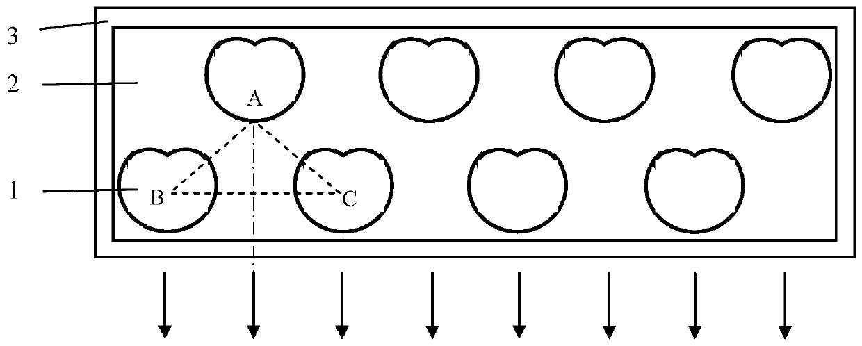
[0016] The number of single laser tubes in the front row of laser lines is 3, and the number of single laser tubes in the rear row of laser lines is 2, such as image 3 As shown, the asymmetric microdisk cavity is an elliptical microdisk cavity, and the ellipse deformation factor ε is defined as the ratio of the major axis to the minor axis of the ellipse. The deformation factor ε = 1.2, and the length of the minor axis is 120 μm. The distances AB and AC between the light exit point A of the single laser tube in the rear row of laser lines and the geometric centers B and C of the two closest laser tubes in the front row of laser lines are equal, and the angle between AB and AC is ∠ A=60°, AB=AC=500 μm, from which it can be calculated that the geometric center distance of two adjacent laser single tubes in the front row of laser lines is about 500 μm, offsetting the transverse radius of the two elliptical microdisk cavities, The transverse radius of the cavity is the length of ...
Embodiment 3
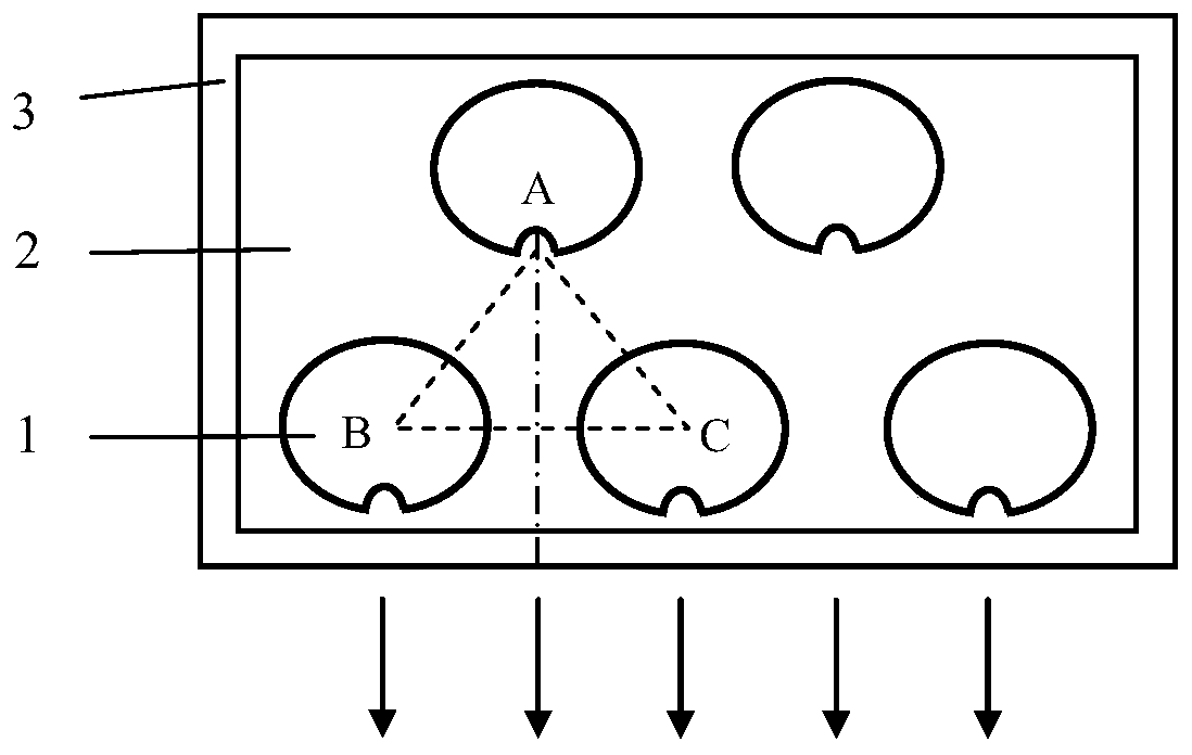
[0018] The number of single laser tubes in the front row of laser lines is 3, and the number of single laser tubes in the rear row of laser lines is 2, such as Figure 4 As shown, the asymmetric microdisk cavity is a spiral microdisk cavity, and the helix polar coordinate equation of the spiral microdisk cavity is Where ρ(θ) is the polar diameter, ρ 0 is the characteristic radius, θ is the polar angle, ε is the deformation factor, and ρ 0 As the characteristic radius of the spiral microdisk cavity, take ρ 0= 200 μm, ε = 0.1. The distances AB and AC between the light exit point A of the single laser tube in the rear row of laser lines and the geometric centers B and C of the two closest laser tubes in the front row of laser lines are equal, and the angle between AB and AC is ∠ A=90°, AB=AC=900 μm, from which it can be calculated that the geometric center distance of two adjacent laser single tubes in the front row of laser lines is about 1270 μm, offsetting the characterist...
PUM
| Property | Measurement | Unit |
|---|---|---|
| length | aaaaa | aaaaa |
| length | aaaaa | aaaaa |
| length | aaaaa | aaaaa |
Abstract
Description
Claims
Application Information
 - R&D Engineer
- R&D Manager
- IP Professional
- Industry Leading Data Capabilities
- Powerful AI technology
- Patent DNA Extraction
Browse by: Latest US Patents, China's latest patents, Technical Efficacy Thesaurus, Application Domain, Technology Topic, Popular Technical Reports.
© 2024 PatSnap. All rights reserved.Legal|Privacy policy|Modern Slavery Act Transparency Statement|Sitemap|About US| Contact US: help@patsnap.com