Pad detecting device

A technology for detection devices and pads, which is applied in the direction of measuring devices, optical devices, instruments, etc., can solve problems such as low precision, leaks, and fatigue detection, and achieve the effects of reducing labor costs, improving detection efficiency, and avoiding false detections

Pending Publication Date: 2019-06-21
广州佳昕机电科技有限公司
View PDF0 Cites 2 Cited by
  • Summary
  • Abstract
  • Description
  • Claims
  • Application Information

AI Technical Summary

Problems solved by technology

However, manual visual inspection has low efficiency, slow speed, and low precision, and labor costs and management costs are increasing year by year.
In addition, the working hours of workers are limited, and they are prone to fatigue and cause detection errors.

Method used


Image

  • Pad detecting device
  • Pad detecting device
  • Pad detecting device

Examples


Embodiment Construction

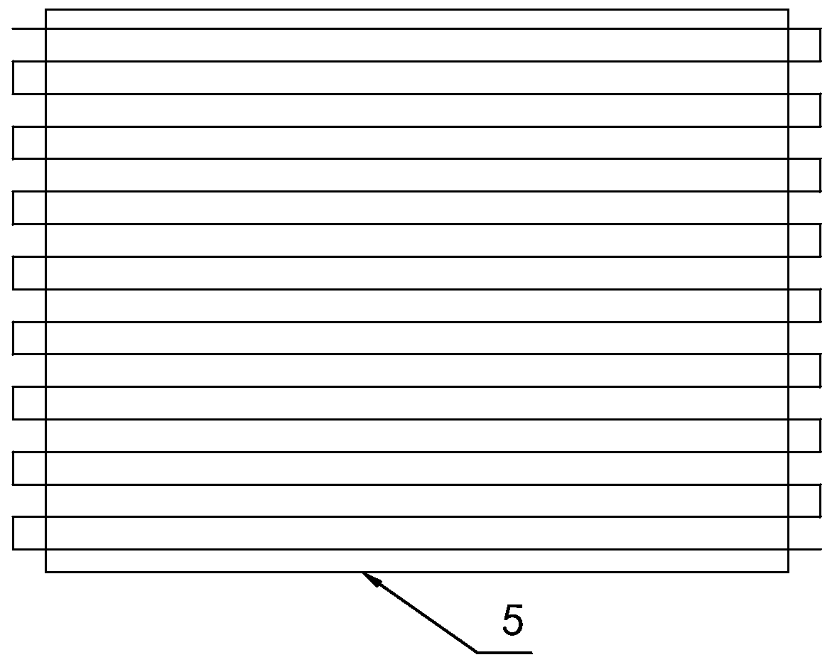
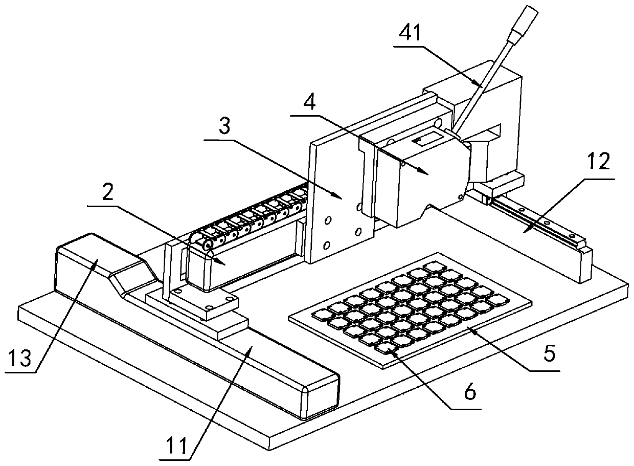
[0018] refer to figure 1 with figure 2 , The present invention is a pad detection device, including a first guide rail, a second guide rail 2, a laser rangefinder 4, a stage 5, a first drive device and a second drive device. The first guide rail is generally perpendicular to the second guide rail 2 , and the first guide rail and the second guide rail 2 are generally set to be horizontal for the pad detection device. Usually both the first driving device and the second driving device are motors. The second guide rail 2 moves along the first guide rail driven by the first driving device, and the laser range finder 4 moves along the second guide rail 2 driven by the second drive device. Driven by the first guide rail and the second guide rail 2, the laser rangefinder 4 can realize horizontal two-dimensional movement. Usually, the stage 5 is set to be flat, and is used to place the components to be tested 6 . The laser range finder 4 faces the object stage 5. Since a pluralit...


PUM


Abstract

The invention discloses a pad detecting device, which comprises a first guiding rail, a second guiding rail, a laser range finder, an object stage, a first driving device and a second driving device,wherein the second guiding rail is driven by the first driving device to move along the first guiding rail; the laser range finder is driven by the second driving device to move along the second guiding rail; the object stage is flat; and the laser range finder faces the object stage. According to the pad detecting device disclosed in the invention, a detected element is placed on the object stage, the laser range finder scans the detected element from different positions, the flatness of the detected element can be effectively detected, the flatness of the pad in the detected element can be detected accurately and efficiently, a qualified element can thus be selected, the welding quality of the element is ensured, the production quality of a product is enhanced, the phenomena of false detection, misdetection and missed detection by the traditional manual visual detection can be avoided, the detection efficiency is effectively improved, and the manual cost is reduced. The pad detectingdevice is used in the field of detecting equipment.

Description

technical field [0001] The invention relates to the field of detection equipment, in particular to a pad detection device. Background technique [0002] Generally, in order to make the structure more compact and the installation more convenient, the car speakers are usually set as SMD components. In the SMD speaker, metal pads are usually provided. Among them, the pads are connected to the positive and negative poles of the power supply of the speaker, and sometimes some auxiliary pads are set to make the speaker more stable. In order to ensure the quality of welding and achieve a better use effect of the car speaker, it is usually necessary to ensure the flatness of the pad itself and the relative flatness between the pads, that is, to ensure that the solder contact area of ​​each pad and the car speaker flatness. However, since the material of the pad is a thin metal sheet, and a part of the thin metal sheet is suspended. Therefore, it is easy to deform during the prod...

Claims


Application Information

Patent Timeline
Patent Type & Authority Applications(China)
IPC IPC(8): G01B11/30
Inventor 王贝
Owner 广州佳昕机电科技有限公司
Why Eureka
Try Eureka