
Ventilating and air blowing device and ventilating and air blowing equipment made by ventilating and air blowing device

A technology of ventilation fan and blower device, which is applied to components of pumping devices for elastic fluids, pump devices, mechanical equipment, etc., and can solve problems affecting fitness, contradictory individual needs of equipment, and inability to meet individual fitness needs. , to achieve the effect of highlighting the substantive characteristics

Inactive Publication Date: 2019-06-21
周洪广
View PDF0 Cites 0 Cited by
  • Summary
  • Abstract
  • Description
  • Claims
  • Application Information

AI Technical Summary

Problems solved by technology

[0008] In view of the above-mentioned "sub-fitness" problem, the existing technology often uses fresh air fans, air conditioners, ventilators, electric fans and other equipment to alleviate them. The difference is that the functions of the above-mentioned equipment cannot meet the needs of individual fitness. Collective public use of these equipment sometimes creates conflicts between individual needs and can even affect fitness. Therefore, breaking through the indoor and outdoor barriers to solve the "sub-fitness" problem of indoor sports is a top priority!

Method used


Image

  • Ventilating and air blowing device and ventilating and air blowing equipment made by ventilating and air blowing device
  • Ventilating and air blowing device and ventilating and air blowing equipment made by ventilating and air blowing device
  • Ventilating and air blowing device and ventilating and air blowing equipment made by ventilating and air blowing device

Examples


Embodiment Construction

[0043] In order to make the problems to be solved, technical solutions and beneficial effects of the present invention clearer, the present invention will be further described in detail below in conjunction with the accompanying drawings and embodiments. It should be understood that the specific examples described herein do not limit the invention.

[0044] The implementation of the present invention will be described in detail below in conjunction with specific drawings, which are only a few preferred specific examples.

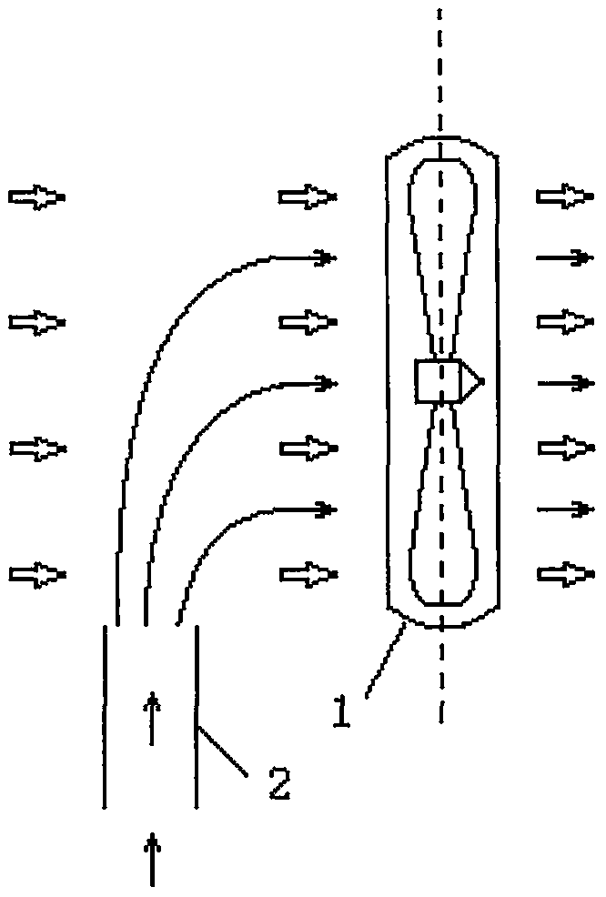
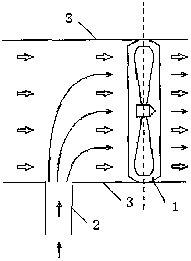
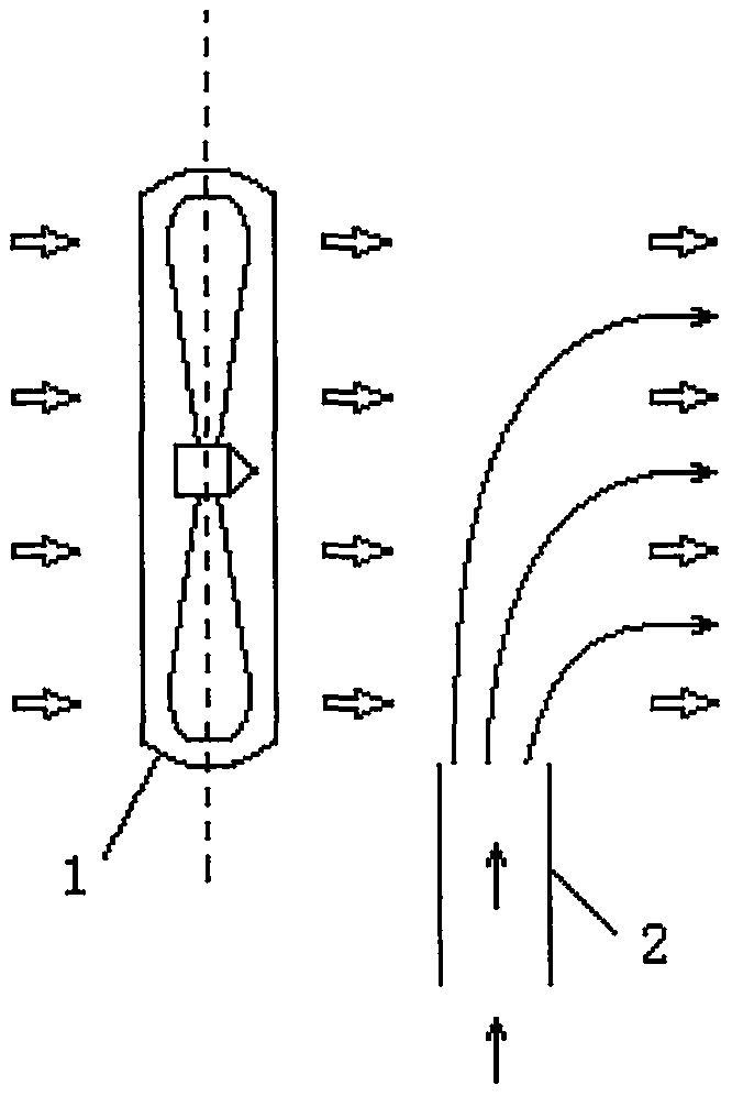
[0045] figure 1 , 2 , 3, 4 are schematic diagrams of four basic embodiments of ventilation fan device of the present invention, wherein: figure 1 , 2 It is a schematic diagram of the air transmission channel set at the air inlet end of the fan device, image 3 , 4 It is a schematic diagram of the air delivery channel set at the air outlet end of the fan device.

[0046] exist figure 1 , 3 Set fan channel 3 on the basis of figure 2 , 4 . In this s...


PUM


Abstract

The invention discloses a ventilating and air blowing device and ventilating and air blowing equipment made by the ventilating and air blowing device, and relates to the technical field of ventilatingand air blowing. According to the ventilating and air blowing device, an air blowing device is arranged at the tail end of a fresh air conveying channel, so that fresh air is conveyed by the air blowing device together with the tail end of the fresh air conveying channel; the ventilating and air blowing device besides has the functions of a traditional fresh air ventilator and a traditional electric fan, and specially can mix air sources of the fresh air and the air blowing device together, so that an air supply effect of blowing indoor air and / or outdoor air can be achieved; and according tothe ventilating and air blowing device, the air supply performance of a traditional fresh air ventilating device is further optimized, the fresh air supply direction can be more flexible, the air supply distance is longer, and the range is wider. According to the ventilating and air blowing device, through the combination of the air blowing device and the fresh air conveying channel, a series ofthe ventilating and air blowing equipment with brand new concepts can be manufactured, and the equipment has the functions of ventilating, air blowing and oxygen supplying, and has the characteristicsthat air directions and air volume can be flexibly adjusted, the air sources can be switched conveniently, air adding or air mixing ratio is easy to adjust, and the novel natural air can be easily generated.

Description

technical field [0001] The invention belongs to the technical field of ventilation fans, and relates to a ventilation fan device and a ventilation fan device made of the ventilation fan device. Background technique [0002] With regard to the current state of the art related to the present invention, people can promote health and improve work efficiency in fresh air. When there is no window or there is no wind outside, when the indoor air is bad, it is still a problem to be solved to keep the indoor air fresh. [0003] The existing fresh air device can solve this problem very well, but it cannot supply air to individuals. Most of the current air supply outlets of fresh air devices are fixed on the ceiling, and they are mostly used as replacement air for the indoor environment. They do not deliver fresh air to individuals. Breathe fresh outdoor air directly indoors. Secondly, it can’t fan the wind. The wind speed, air supply distance, and sweeping range of the air outlet of...

Claims


Application Information

Patent Timeline
IPC IPC(8): F04D25/08F04D25/16F04D29/52
Inventor 周洪广
Owner 周洪广
Learn More