Clamping device, downhole tool and downhole release structure
A fixed and working technology, which is applied in the field of natural gas and oil exploration, can solve the problems of difficult disassembly and replacement of downhole tools and high cost, and achieve the effect of convenient disassembly and simple fixation
- Summary
- Abstract
- Description
- Claims
- Application Information
AI Technical Summary
Problems solved by technology
Method used
Image
Examples
Embodiment 1
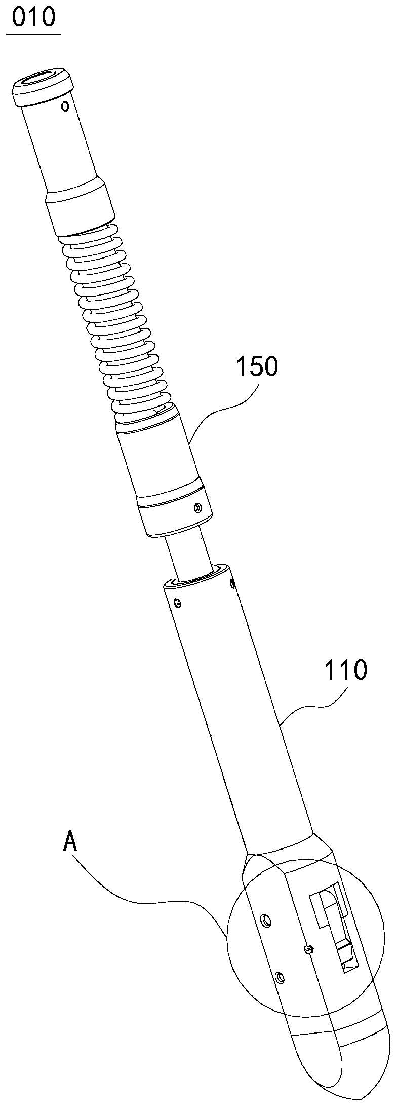
[0057] This embodiment provides a locking device 010 . figure 1 It is a schematic diagram of the external structure of the locking device 010 provided in the embodiment of the present application. figure 2 It is a schematic cross-sectional structure diagram of the locking device 010 provided in the embodiment of the present application, wherein the extruding part 120 is located at the evacuation position. image 3 It is a schematic cross-sectional structure diagram of the locking device 010 provided in the embodiment of the present application, wherein the extruding member 120 is located at the extruding position.
[0058] Please refer to figure 1 , figure 2 and image 3 , In this embodiment, the locking device 010 includes a working column 110 , an extruding part 120 , a power mechanism 130 and a locking part 140 .
[0059] An axial channel 111 extending in the axial direction is opened on the working column 110 . One end of the axial channel 111 is open, and the other...
Embodiment 2
[0072] This embodiment provides a locking device 020 . Figure 8 It is a schematic cross-sectional structure diagram of the locking device 020 provided in the embodiment of the present application, wherein the extruding part 220 is located in the vacated position. Figure 9 It is a schematic cross-sectional structure diagram of the locking device 020 provided in the embodiment of the present application, wherein the extruding member 220 is located at the extruding position.
[0073] Please refer to Figure 8 and Figure 9 , In this embodiment, the locking device 020 includes a working column 210 , an extruding part 220 , a power mechanism 230 and a locking part 240 .
[0074] An axial channel 211 extending in the axial direction is opened on the working column 210 . Both ends of the axial channel 211 are open, and the other end of the axial channel 211 is closed. A radial channel 212 extending in the radial direction is also opened on the working column 210 . The radial c...
Embodiment 3
[0080] This embodiment provides a downhole tool 030 . Figure 10 A schematic structural diagram of the downhole tool 030 provided in this embodiment. The downhole tool 030 provided in this embodiment includes the locking device 010 described in the first embodiment or the locking device 020 described in the second embodiment. In this embodiment, the locking device 010 described in Embodiment 1 is taken as an example for description. The downhole tool 030 provided in this embodiment further includes a function executing component 400 installed on the locking device 010 . The function executing component 400 can be conveniently fixed at a predetermined position in the oil and gas well along with the locking device 010 , and can also be easily disassembled from the oil and gas well along with the locking device 010 .
[0081] The function executing component 400 is a component capable of realizing a certain function in an oil and gas well, such as a temperature detection device...
PUM
 Abstract
Description
Claims
Application Information
 - R&D
- Intellectual Property
- Life Sciences
- Materials
- Tech Scout
- Unparalleled Data Quality
- Higher Quality Content
- 60% Fewer Hallucinations
Browse by: Latest US Patents, China's latest patents, Technical Efficacy Thesaurus, Application Domain, Technology Topic, Popular Technical Reports.
© 2025 PatSnap. All rights reserved.Legal|Privacy policy|Modern Slavery Act Transparency Statement|Sitemap|About US| Contact US: help@patsnap.com


