
A graph-based detection method for flow pulsation characteristics of multi-pump confluence

A flow pulsation and detection method technology, applied in the direction of measuring devices, measuring rapid changes, instruments, etc., can solve the problems of high cost, low efficiency, and inability to provide theoretical basis for multi-pump system design and development, and achieve simple calculation and satisfactory calculation accuracy Effect

Active Publication Date: 2020-08-18
TONGJI UNIV
View PDF5 Cites 0 Cited by
  • Summary
  • Abstract
  • Description
  • Claims
  • Application Information

AI Technical Summary

Problems solved by technology

The pulsation characteristics of the confluence flow in a multi-pump oil supply system can be obtained by superimposing the instantaneous flow of each pump, but the start-up time of each pump is related to the actual working conditions of the equipment, resulting in uncertainty in the pulsation characteristics of the confluence instantaneous flow, and the working flow pulsation of the multi-pump system The theoretical basis of the characteristics is lacking, and the determination of the confluence flow pulsation characteristics based on experiments has the disadvantages of high cost and low efficiency, which cannot provide a theoretical basis for the design and development of more efficient and low flow pulsation multi-pump systems

Method used


Image

  • A graph-based detection method for flow pulsation characteristics of multi-pump confluence
  • A graph-based detection method for flow pulsation characteristics of multi-pump confluence
  • A graph-based detection method for flow pulsation characteristics of multi-pump confluence

Examples


specific Embodiment

[0052] This embodiment provides a method for detecting the pulsation characteristics of the confluent flow of a three-way pump. The main steps of the method are shown in Fig. figure 1 shown.

[0053] In this example, the three pumps are all plunger pumps with 7 plungers. When each pump works independently, its geometric flow function is The instantaneous flow function is a periodic function with a period of β, and the period of the combined flow function is still β. The average flow is 2K sin(β / 2) / β. K is a coefficient related to the structure and speed of the plunger pump itself, K=ωπd 2 R tan α / (8 sinβ / 2), ω is the speed of the pump, d is the diameter of the plunger, R is the radius of the distribution circle where the plunger axis is located, and β is half of the angle between two adjacent plungers, that is, β=π / Z, Z is the plunger number.

[0054] When the three pumps are combined, for the first pump, the flow function is:

[0055]

[0056] In the formula, is t...


PUM


Abstract

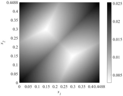
The invention relates to a graph-based detection method of a multi-pump confluence flow pulsation characteristic. The graph-based detection method comprises the steps that 1, according to a type of apump, an instantaneous flow function and an average flow when each pump works independently are obtained by using a pump flow theoretical model or a flow pulsation experimental result; 2, a pump angleis arbitrarily chosen as a foundation rotation angle, and the rotation angle phase difference random characteristic and the foundation rotation angle range between other pumps and the pump are determined; 3, the instantaneous flow function and the average flow are calculated when the multiple pumps work together; 4, a multivariate function relationship between the confluence flow pulsation rate and each rotation angle phase difference is determined by calculating and is represented graphically; and 5, a graph in the step 4 is used for calculating probability corresponding to the confluence flow pulsation rate in the pulsation rate range. Compared with the prior art, the graph-based detection method is convenient in calculation and can meet requirements of engineering accuracy, and can provide theoretical basis for designing the multi-pump system, suppressing system flow pulsation, and reducing noise and vibration.

Description

technical field [0001] The invention relates to a detection technology of a hydraulic transmission system, in particular to a graph-based detection method for multi-pump confluence flow pulsation characteristics. Background technique [0002] The hydraulic transmission system has the advantages of high power density, low noise and vibration, and stable speed. It is widely used in transportation tools and mechanical equipment such as aerospace, ships, construction machinery, and general industrial equipment. Due to the high power demand of the application, the hydraulic system is developing in the direction of high pressure and large flow, and the pump combined oil supply method has a significant energy saving effect. Due to the limitation of the structure of the pump, the hydraulic system has pulsating changes in the output flow. The pulsation of the flow will cause the pressure pulsation, and the pressure pulsation will easily cause the vibration or noise of the hydraulic p...

Claims


Application Information

Patent Timeline
Patent Type & Authority Patents(China)
IPC IPC(8): G01L23/00G06F17/15G06F17/18
Inventor 李晶何承鹏
Owner TONGJI UNIV
Learn More