Spiral conveying beam for concrete material transportation

A technology of spiral transmission and concrete, which is applied in the direction of conveyor objects, transportation and packaging, etc., can solve the problems of reducing the service life of the device, inconvenient installation of the device, and noise of the conveyor belt, so as to increase the service life, work efficiently and reduce noise. Effect

Inactive Publication Date: 2019-06-18
HUNAN SOFTWARE VOCATIONAL INST
View PDF0 Cites 0 Cited by
  • Summary
  • Abstract
  • Description
  • Claims
  • Application Information

AI Technical Summary

Problems solved by technology

[0003] The existing material conveying devices for construction have certain defects in design. First, the general conveying device is a large-scale conveying arm, which often needs a fixed support point when fixing, and ordinary walls or beams are not competent, resulting in The installation of the device is inconvenient. Secondly, ordinary construction material conveying devices often work through conveyor belts and pulleys. During the material transportation process, the friction of the conveyor belt will bring a lot of noise, and the friction will reduce the service life of the device. The pulley Use will make the device very easy to shake during the transportation process

Method used


Image

  • Spiral conveying beam for concrete material transportation
  • Spiral conveying beam for concrete material transportation
  • Spiral conveying beam for concrete material transportation

Examples


Embodiment Construction

[0018] The technical solutions of the present invention will be further described below in conjunction with the drawings and specific embodiments.

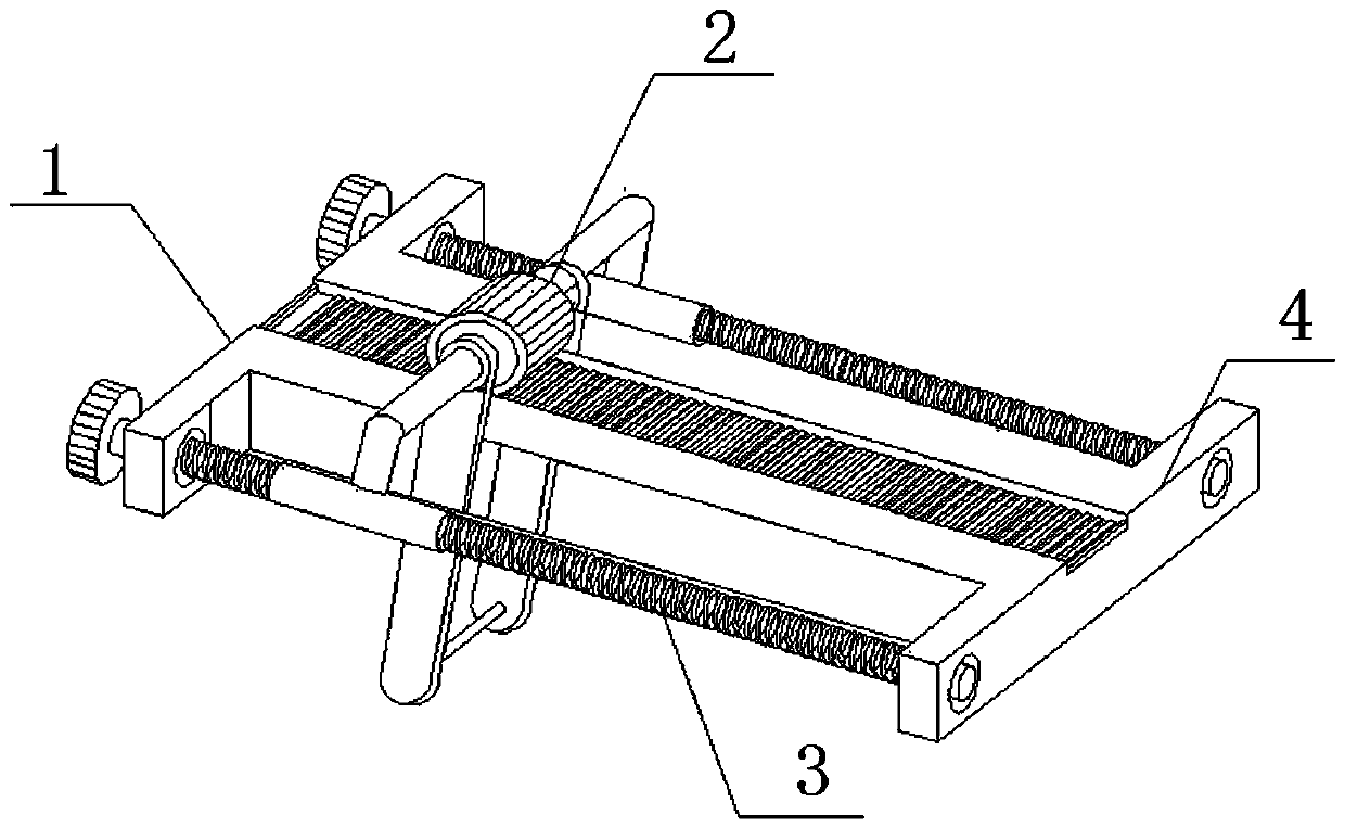
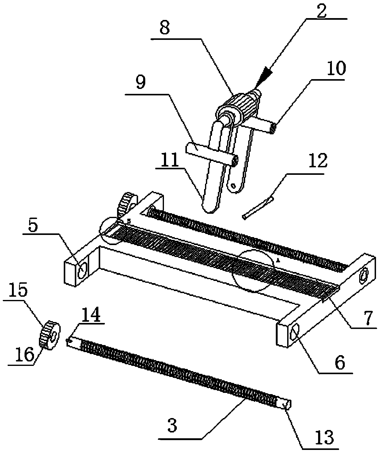
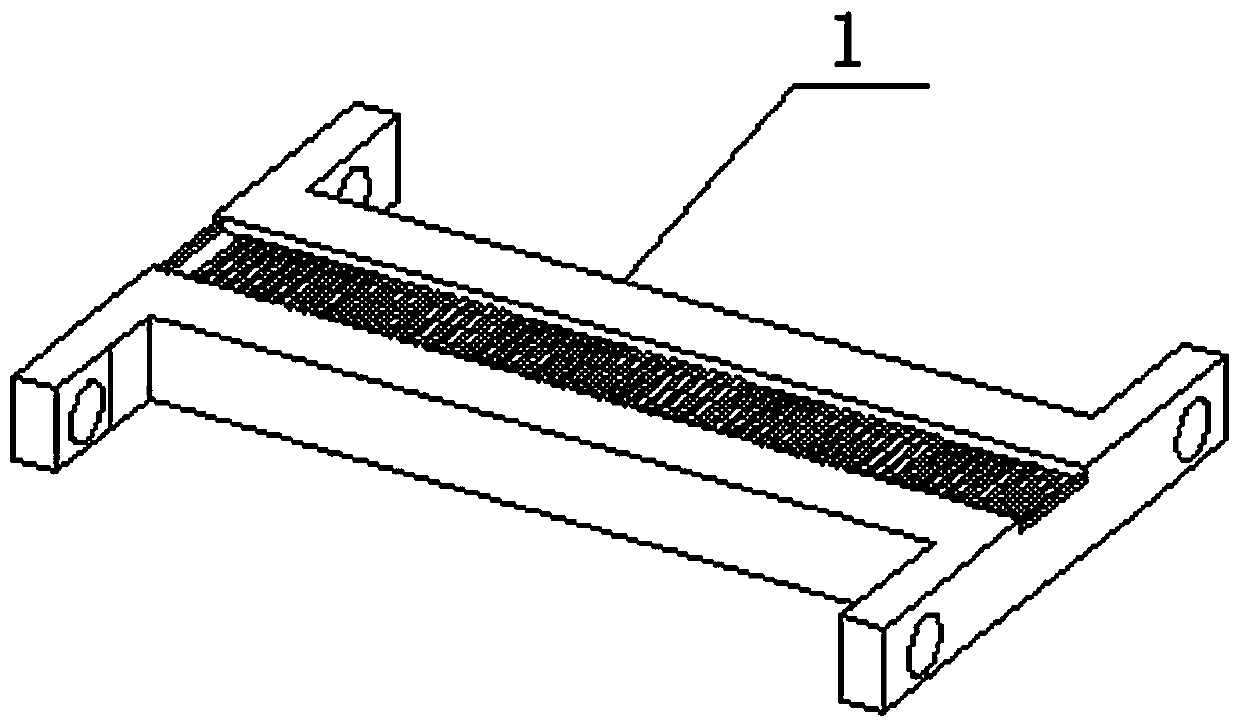
[0019] Such as Figure 1-5 As shown, a spiral conveying beam for conveying concrete materials includes a support beam 1, a suspension assembly 2, and a shape-shifting screw 3. The suspension assembly 2 is installed in the middle of the support beam 1, and two shape-shifting screws are installed on one side of the support beam 1. 3. The connecting block 4 at one end of the supporting beam 1, the limit hole 5 and the rotation hole 6 are set in the middle of the connecting block 4, the chute 7 is set in the middle of the top of the supporting beam 1, the suspension assembly 2 includes a roller 8 and a suspension rod 11, and one side of the roller 8 Several bolts 9 are installed, screw ports 10 are arranged inside several bolts 9, suspension rods 11 are installed on one side of several bolts 9, support rods 12 are installed on one sid...


PUM


Abstract

The invention discloses a spiral conveying beam for concrete material transportation. The spiral conveying beam comprises a supporting cross beam, a hanging assembly and moving screw rods, wherein thehanging assembly is arranged in the middle of the supporting cross beam, one side of the supporting cross beam is provided with the two moving screw rods, each end of the supporting cross beam is provided with a connecting block, a sliding groove is formed in the middle of the top of the supporting cross beam, the hanging assembly comprises a roller and hanging rods, each side of the roller is provided with a bolt, one sides of the bolts are provided with the hanging rods, one sides of the bottoms of the hanging rods are provided with a supporting rod, mandrels are arranged in the middles ofthe moving screw rods, connecting rods are arranged at one ends of the moving screw rods, and rotating motors are arranged at one ends of the moving screw rods. According to the spiral conveying beamfor the concrete material transportation, rotation of the screw rods are used for driving parts to move, the bolts are driven by threads which are meshed with the screw rods, so that the noise problemwhich is difficult to solve by a traditional conveying device is effectively reduced.

Description

technical field [0001] The invention relates to a spiral conveying beam for concrete material conveying. Background technique [0002] With the rapid rise of the modern construction industry, various conceptual buildings have begun to appear in real life. During the construction process, building materials often need to be transported by leaps and bounds. In the past, material transportation was often carried out by manpower. Some conveying machinery will also be used. These machinery can support heavy objects and drive materials to move with a certain power. They play an important role in some transportation areas that cannot be reached by manpower. [0003] The existing material conveying devices used in construction have certain defects in design. First, the general conveying device is a large-scale conveying arm, which often needs a fixed support point when fixing, and ordinary walls or beams are not competent, resulting in The installation of the device is inconvenient...

Claims


Application Information

Patent Timeline
IPC IPC(8): B65G47/74
Inventor 杨静宇
Owner HUNAN SOFTWARE VOCATIONAL INST
Why Eureka
Try Eureka