Automatic filling system and production method for emulsion explosive
An automatic filling system, a technology of emulsion explosives, applied in packaging, ammunition, transportation and packaging, etc., to achieve the effect of improving bagging efficiency, reducing difficulty, and fast automatic filling
- Summary
- Abstract
- Description
- Claims
- Application Information
AI Technical Summary
Problems solved by technology
Method used
Image
Examples
Embodiment 1
[0046] Embodiments of the present invention are described in detail below, examples of which are shown in the drawings, wherein the same or similar reference numerals designate the same or similar elements or elements having the same or similar functions throughout. The embodiments described below by referring to the figures are exemplary and are intended to explain the present invention and should not be construed as limiting the present invention.
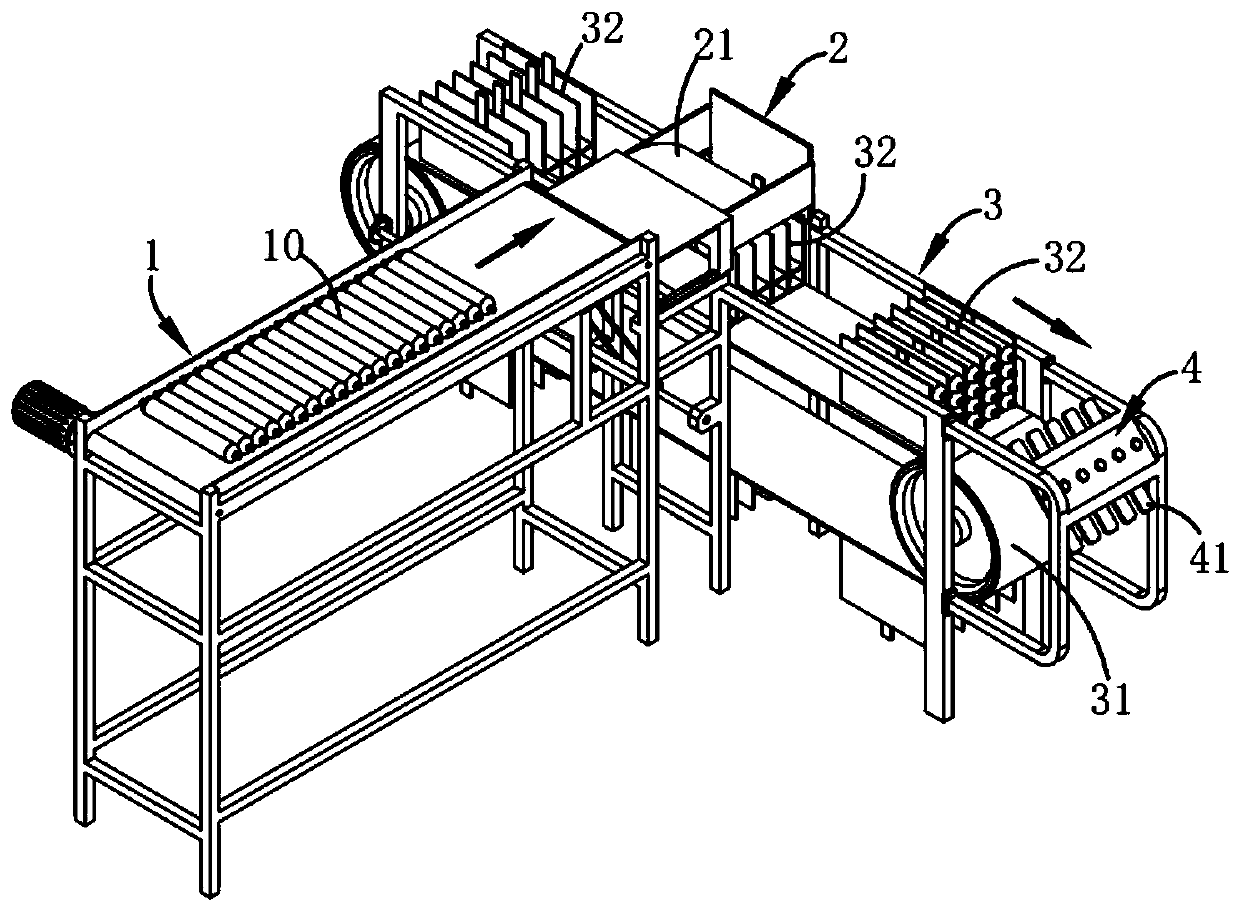
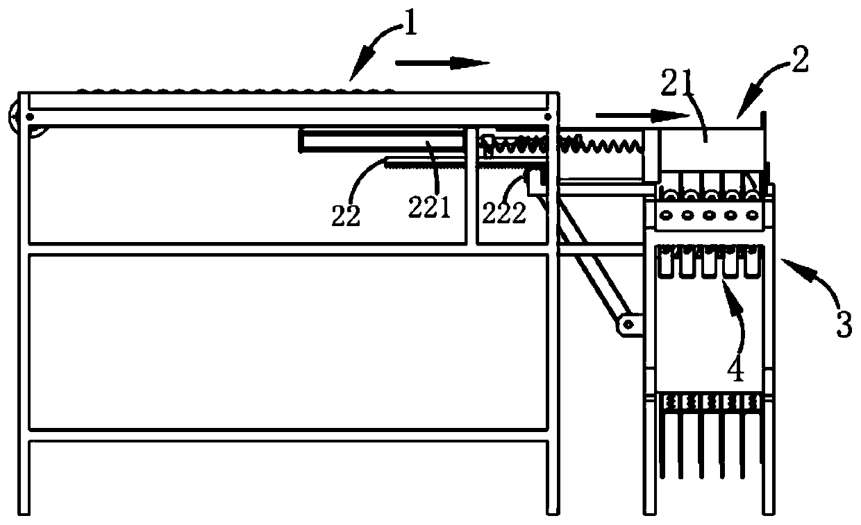
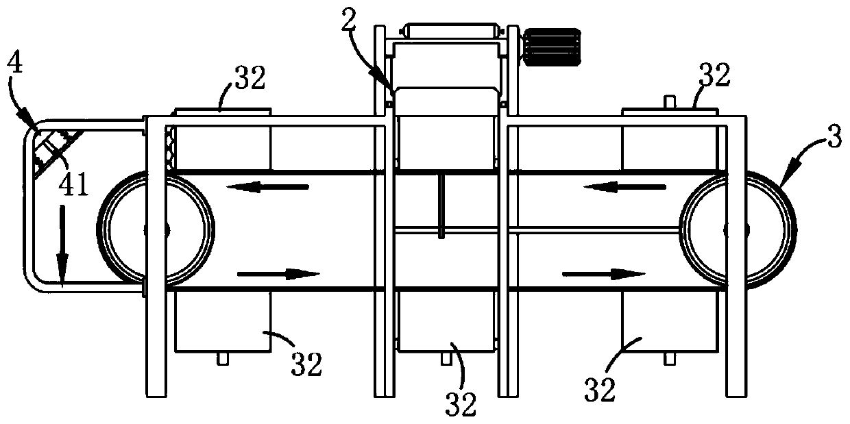
[0047] Such as Figures 1 to 7 As shown, an automatic filling system for emulsion explosives includes a conveying mechanism 1 for directional conveying of finished emulsion explosives 10. The conveying mechanism 1 is provided with a belt conveying structure. 1 The direction of transmission is vertical, also includes:
[0048] Distributing mechanism 2, described distributing mechanism 2 is positioned at the output end of described conveying mechanism 1, and this distributing mechanism 2 comprises the blanking assembly 21 that sli...
Embodiment 2
[0056] Such as Figure 8 and 9 As shown, the parts that are the same as or corresponding to those in Embodiment 1 adopt the reference numerals corresponding to Embodiment 1. For the sake of simplicity, only the differences between Embodiment 1 and Embodiment 1 are described below; the differences between Embodiment 2 and Embodiment 1 The advantage is that the blanking assembly 21 includes a blanking part 211 that is slidably arranged and a traction part 212 that drives the blanking part 211 to move directionally. The blanking part 211 includes a sliding seat 2111, a receiving plate 2112, a blanking Plate 2113 and limit plate 2114, the material receiving plate 2112, blanking plate 2113 and limit plate 2114 are distributed sequentially along the transmission direction of the conveying mechanism 1 and are all arranged on the slide seat 2111, the limit plate 2114 is a plate structure arranged vertically.
[0057] Among them, such as Figure 8 and 9 As shown, the material recei...
Embodiment 3
[0059] Such as figure 2 , 8 , 9 and 10, wherein the same or corresponding parts with the second embodiment adopt the corresponding reference numerals with the second embodiment, for the sake of simplicity, only the difference between the second embodiment and the second embodiment is described below; the third embodiment is similar to the second embodiment The difference of Example 2 is that: the material distributing mechanism 2 also includes a driving assembly 22, and the driving assembly 22 includes a pushing part 221 and a transmission part 222, and the pushing part 221 is used to push the charging of a single receiving bin 32 to complete After the blanking assembly 21 is reset, the transmission part 222 is respectively connected with the transmission part 221 and the transfer mechanism 3, and the transfer mechanism 3 is driven by the transmission part 222 for directional intermittent transmission; in this embodiment, a single After the material receiving bin 32 is fille...
PUM
 Abstract
Description
Claims
Application Information
 - R&D
- Intellectual Property
- Life Sciences
- Materials
- Tech Scout
- Unparalleled Data Quality
- Higher Quality Content
- 60% Fewer Hallucinations
Browse by: Latest US Patents, China's latest patents, Technical Efficacy Thesaurus, Application Domain, Technology Topic, Popular Technical Reports.
© 2025 PatSnap. All rights reserved.Legal|Privacy policy|Modern Slavery Act Transparency Statement|Sitemap|About US| Contact US: help@patsnap.com


