
Coding device based on Internet of things control

A technology of Internet of Things control and docking, applied in typewriters, printing and other directions, can solve the problems of high use limitations, inconvenient repair of the left and right cylinders, and achieve the effect of reducing equipment failure rates and use limitations.

Inactive Publication Date: 2019-06-18
NORTH CHINA UNIVERSITY OF SCIENCE AND TECHNOLOGY
View PDF11 Cites 0 Cited by
  • Summary
  • Abstract
  • Description
  • Claims
  • Application Information

AI Technical Summary

Problems solved by technology

[0002] As we all know, a coding device controlled by the Internet of Things is a device for printing and coding items, which has been widely used in the field of coding; existing coding devices controlled by the Internet of Things include workbench , support plate and punching dock, the workbench is provided with a left cylinder and a right cylinder, the output end of the left cylinder is connected to the left wall of the support plate, and the output end of the right cylinder is connected to the right wall of the punching dock; the existing IoT-based control When the coding device is in use, place the item between the support plate and the printing terminal, the left cylinder and the right cylinder work at the same time, the support plate and the printing terminal are close, the support plate supports the item, and the printing terminal prints the code on the outer wall of the object; In the use of the existing coding device based on the Internet of Things control, it is found that it is not convenient to repair when the left and right cylinders fail, and the use limitations are relatively high

Method used


Image

  • Coding device based on Internet of things control
  • Coding device based on Internet of things control
  • Coding device based on Internet of things control

Examples


Embodiment Construction

[0020] The specific embodiments of the present invention will be described in further detail below in conjunction with the drawings and embodiments. The following examples are used to illustrate the present invention, but not to limit the scope of the present invention.

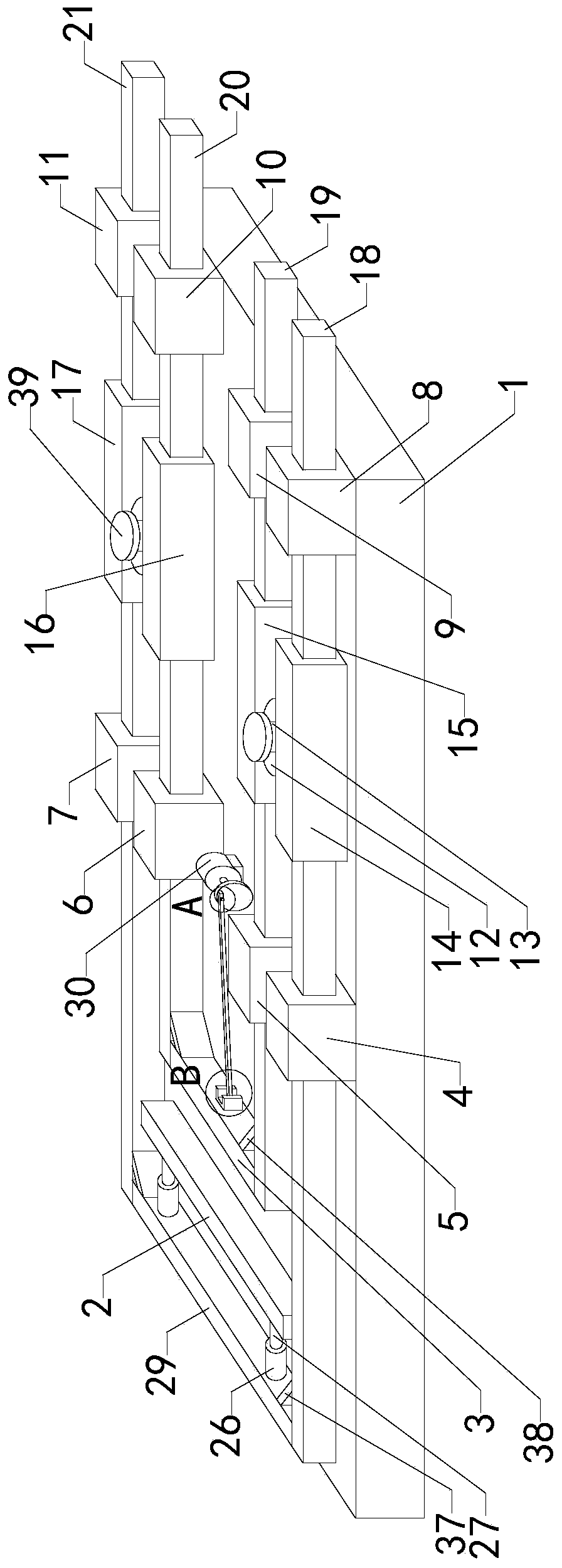
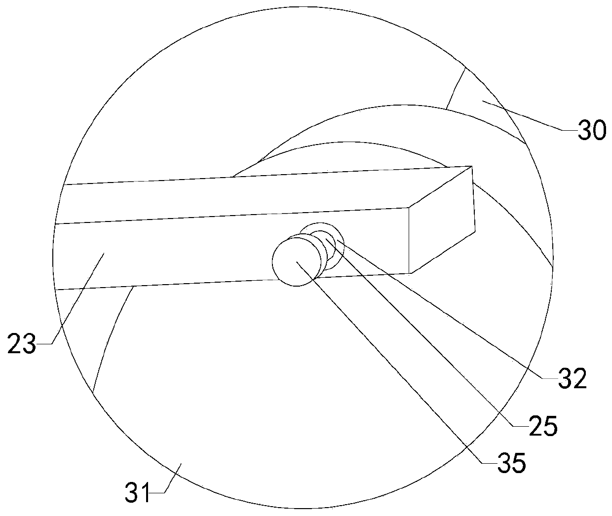
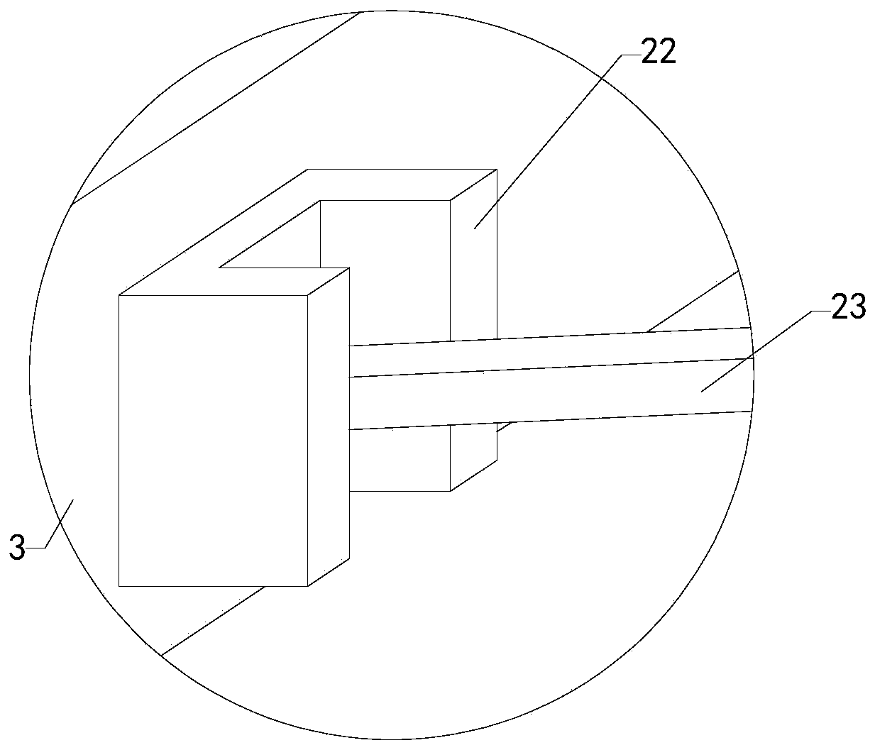
[0021] Such as Figure 1 to Figure 6 As shown, a coding device based on Internet of Things control of the present invention includes a workbench 1, a support plate 2, and a dock 3; also includes a first left fixing ring 4, a second left fixing ring 5, and a third left fixing Ring 6, fourth left fixed ring 7, first right fixed ring 8, second right fixed ring 9, third right fixed ring 10, fourth right fixed ring 11, front gear 12, rear gear, front shaft 13, rear Rotating shaft, first rack 14, second rack 15, third rack 16, fourth rack 17, first sliding rod 18, second sliding rod 19, third sliding rod 20, fourth sliding rod 21, The connecting block 22, the driving rod 23, the left turning rod 24, the right turnin...


PUM


Abstract

The invention relates to the technical field of coding accessory devices, in particular to a coding device based on Internet of things control. The equipment failure rate is reduced, and the use limiting is reduced. The device comprises a worktable, a supporting plate and a coding head and further comprises a first left fixed ring, a second left fixed ring, a third left fixed ring, a fourth left fixed ring, a first right fixed ring, a second right fixed ring, a third right fixed ring, a fourth right fixed ring, a front gear, a rear gear, a front rotating shaft, a rear rotating shaft, a first rack, a second rack, a third rack, a fourth rack, a first sliding rod, a second sliding rod, a third sliding rod, a fourth sliding rod, a connecting block, a driving rod , a left rotating rod, a rightrotating rod, a front fixed rod, a front buffer rod, a front spring, a rear fixed rod, a rear buffer rod, a rear spring and a connecting plate; a motor is arranged on the center area of the top side wall of the worktable, and a driving disc is arranged on the output end of the motor.

Description

Technical field [0001] The present invention relates to the technical field of coding accessory devices, in particular to a coding device based on Internet of Things control. Background technique [0002] As we all know, the coding device based on the Internet of Things control is a device for printing and encoding items, which has been widely used in the field of coding; the existing coding device based on the Internet of Things control includes a workbench , Support plate and wharf, the workbench is provided with left and right cylinders, the output end of the left cylinder is connected with the left side wall of the support plate, and the output end of the right cylinder is connected with the right wall of the wharf; the existing control based on the Internet of Things When the coding device is used, the article is placed between the support plate and the dock, the left and right cylinders work at the same time, the support plate is close to the dock, the support plate support...

Claims


Application Information

Patent Timeline
IPC IPC(8): B41J3/407
Inventor 刘利平赵英娜张文丽贾政权
Owner NORTH CHINA UNIVERSITY OF SCIENCE AND TECHNOLOGY
Learn More