
Rotor structure and switch reluctance motor

A switched reluctance motor, rotor structure technology, applied in the magnetic circuit shape/style/structure, magnetic circuit static parts, magnetic circuit rotating parts, etc. The cost of the motor controller is rising, and the control strategy is complicated. It can improve the electromagnetic torque, reduce the tangential magnetic field force, and optimize the magnetic field distribution.

Inactive Publication Date: 2019-06-14
SOUTH CHINA UNIV OF TECH
View PDF7 Cites 0 Cited by
  • Summary
  • Abstract
  • Description
  • Claims
  • Application Information

AI Technical Summary

Problems solved by technology

However, due to its inherent double salient pole structure, the torque ripple and vibration noise of the switched reluctance motor are relatively large, which restricts its application and promotion.
[0003] In the prior art, most of the suppression of the torque ripple of the switched reluctance motor revolves around the motor controller, and the suppression of the torque ripple is achieved by optimizing the control strategy, current waveform and other methods, but the effect is often limited and will lead to complex control strategies, The cost of motor controllers is rising, which is not conducive to the promotion of motors

Method used


Image

  • Rotor structure and switch reluctance motor
  • Rotor structure and switch reluctance motor
  • Rotor structure and switch reluctance motor

Examples


Embodiment Construction

[0025] The present invention will be further described below in conjunction with drawings and embodiments.

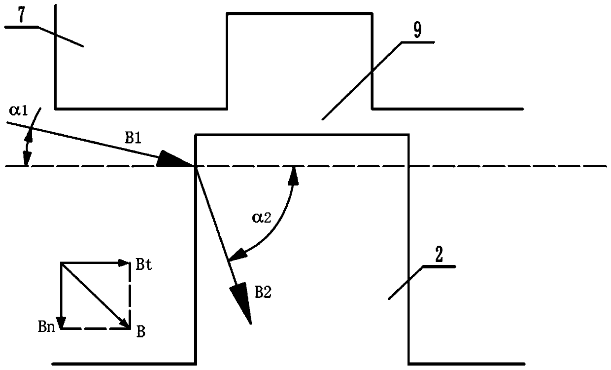
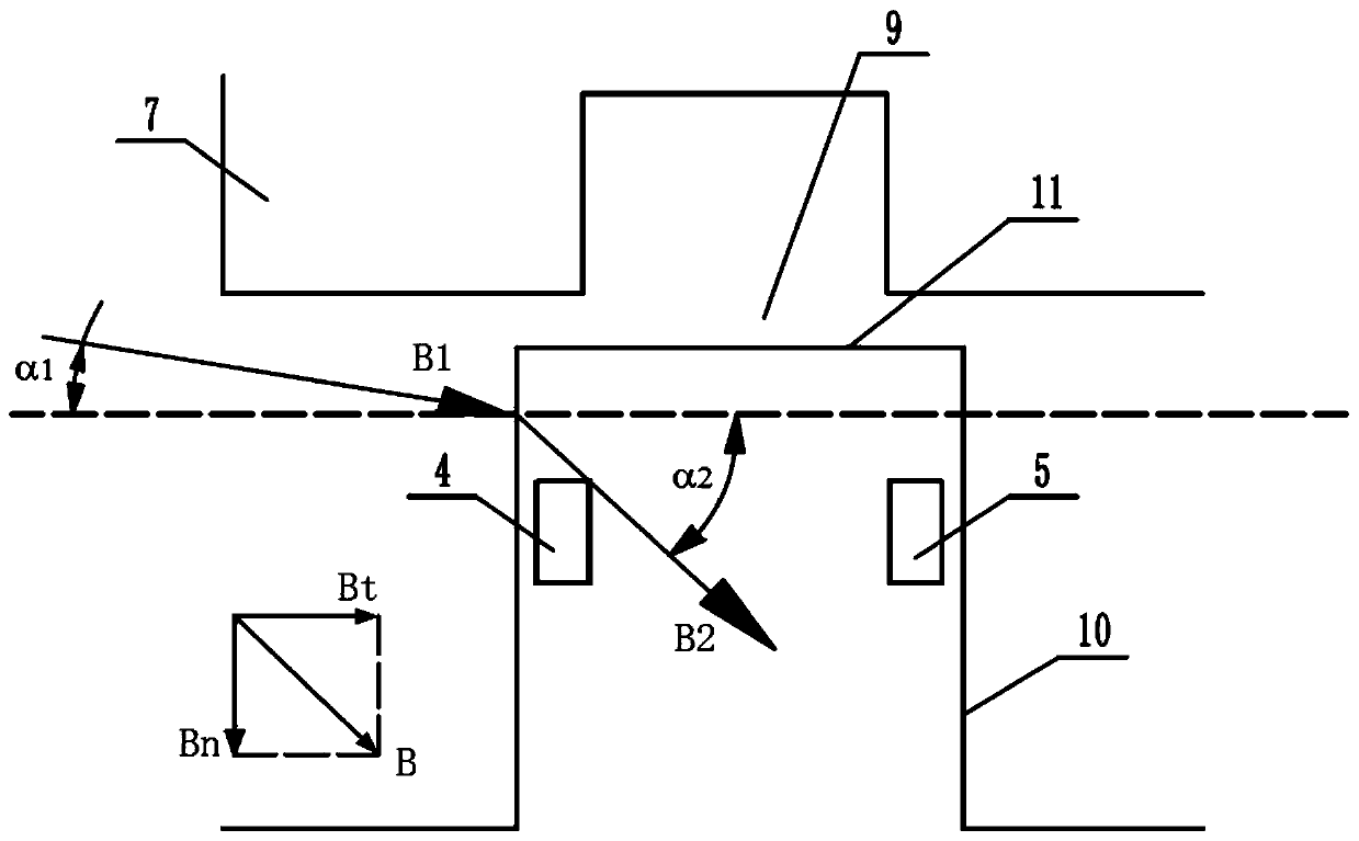
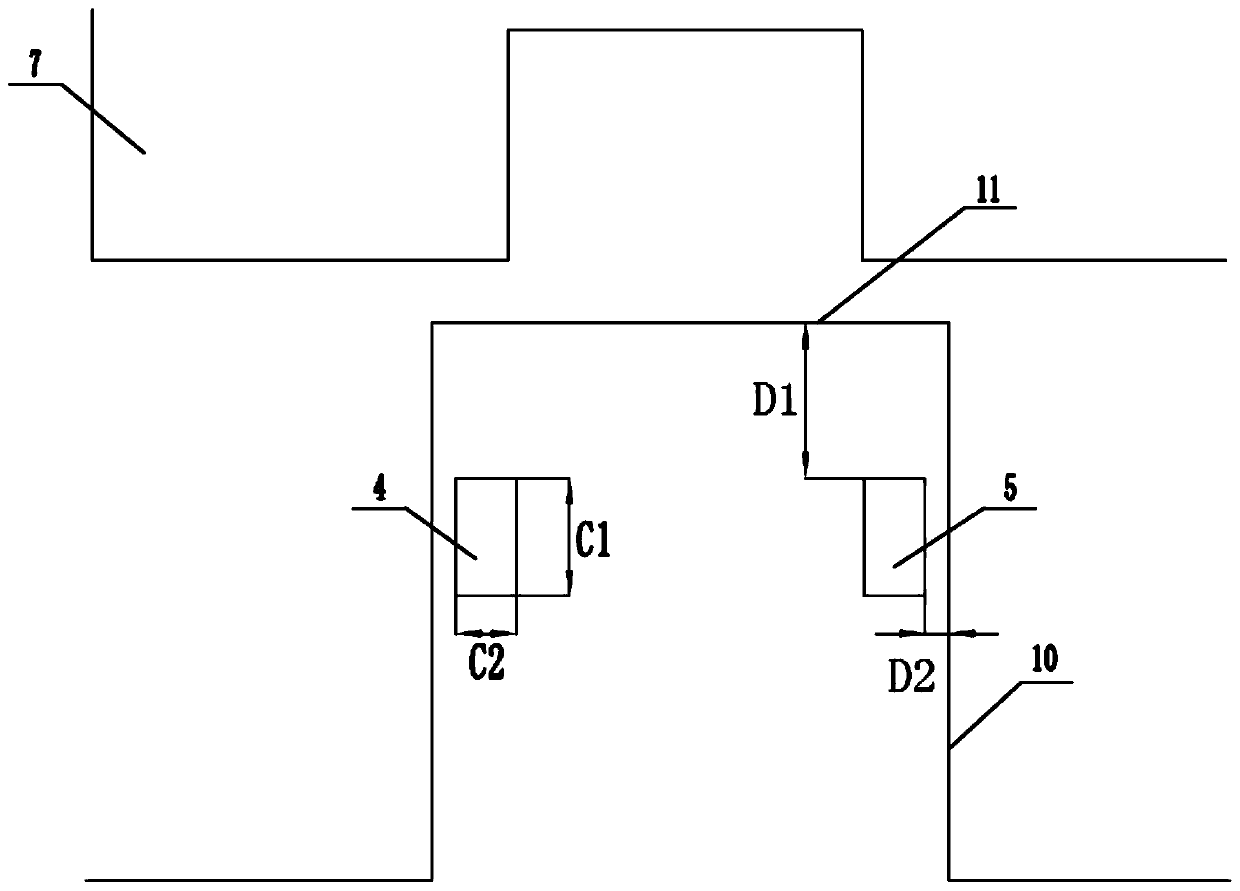
[0026] Such as Figure 1-Figure 3 The rotor structure shown includes a rotor body 1 and a plurality of rotor salient poles 2; the center of the rotor body 1 has a mounting hole 3, and the plurality of rotor salient poles 2 are evenly arranged on the outer periphery of the rotor body 1, And the rotor salient poles 2 protrude outward along the radial direction of the rotor body 1, and a plurality of the rotor salient poles 2 are provided with a first through hole 4 and a second through hole 5 penetrating along its axial direction. . A keyway is provided in the mounting hole 3, and the mounting hole 3 is used for mounting a rotating shaft.

[0027] The first through holes 4 and the second through holes 5 are distributed symmetrically along the central axis of the rotor salient pole 2 . This design ensures the dynamic balance of the rotor during operation, and at the sam...


PUM


Abstract

The invention relates to the technical field of the motor, and discloses a rotor structure. The rotor structure comprises a rotor body and multiple rotor salient poles; a mounting hole is formed at the center of the rotor body; multiple rotor salient poles are uniformly arranged at the periphery of the rotor body, and the rotor salient poles are outwardly protruded along a radial direction of therotor body, and first through holes and second through holes penetrating through the axial directions are formed on multiple rotor salient poles. The invention further discloses a switch reluctance motor adopting the above rotor structure. The rotor structure disclosed by the invention has the advantages of being simple in structure, safe and reliable, and economic and practical; the electromagnetic torque is improved by optimizing the structure of the rotor, and the torque pulse in the motor phase-commutating period is reduced.

Description

technical field [0001] The invention relates to the technical field of motors, in particular to a rotor structure. It also relates to a switched reluctance motor adopting the above-mentioned rotor structure. Background technique [0002] The structure of the switched reluctance motor is simple and reliable. Both the stator and the rotor are laminated by silicon steel sheets. There are only windings on the stator. There is no permanent magnet or winding on the rotor. It has a large starting torque and a small starting current; the rotor There is no cooling requirement, the heat dissipation of the stator is fast, and the overload capacity is strong; a wide range of constant power speed regulation can be realized; each phase winding of the motor works independently, and there is no need to consider the short circuit phenomenon of the switching device, and the fault tolerance is strong; by changing the opening and closing The four-quadrant operation can be easily realized. In r...

Claims


Application Information

Patent Timeline
Patent Type & Authority Applications(China)
IPC IPC(8): H02K1/24H02K1/14
Inventor 梁乔丹兰凤崇陈吉清曾立锵
Owner SOUTH CHINA UNIV OF TECH
Learn More