
Automatic tightness adjusting type belt fastener capable of automatically adjusting tightness of belt

An automatic adjustment, belt buckle technology, applied in the direction of buckles, fasteners, clothing belts, etc., can solve the problems of fine adjustment of belt tightness, belt damage, inability to user experience, etc., to ensure integrity and avoid damage.

Active Publication Date: 2019-06-11
QING CAN XING HARDWARE CRAFTS CO LTD
View PDF5 Cites 3 Cited by
  • Summary
  • Abstract
  • Description
  • Claims
  • Application Information

AI Technical Summary

Problems solved by technology

[0007] The purpose of the present invention is to solve the shortcomings in the prior art, such as: because the abdomen of a person is changing every moment, the belt buckle cannot fine-tune the tightness of the belt, resulting in that the tightness of the belt cannot adapt to the abdomen. changes, and thus cannot give users a better experience, because the end of the belt without a belt hole is fixed on the belt buckle. Generally, the fixed belt is inserted into the belt through a row of fixed teeth on the fixed block to fix the belt. However, this The fixing method directly caused damage to the belt

Method used


Image

  • Automatic tightness adjusting type belt fastener capable of automatically adjusting tightness of belt
  • Automatic tightness adjusting type belt fastener capable of automatically adjusting tightness of belt
  • Automatic tightness adjusting type belt fastener capable of automatically adjusting tightness of belt

Examples


Embodiment 2

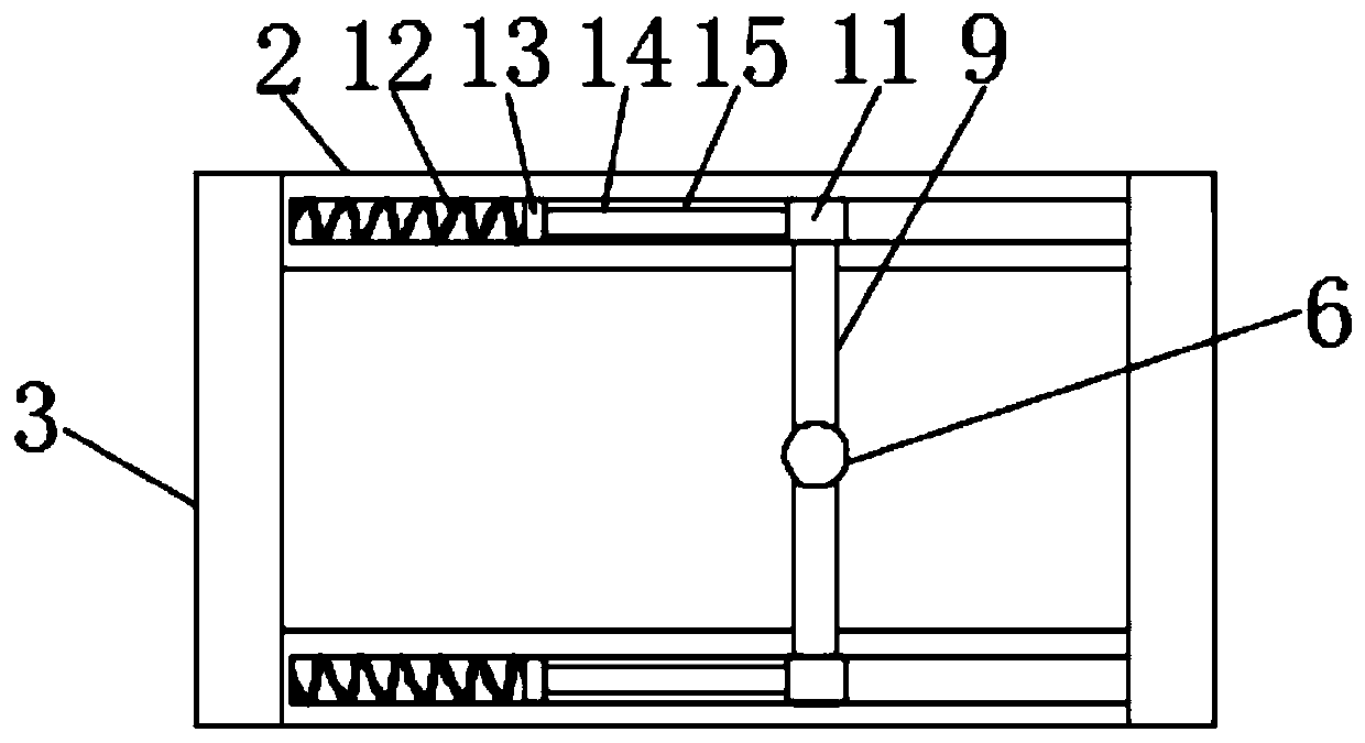
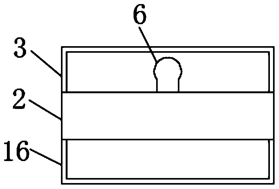
[0035]The difference between the second embodiment and the first embodiment is that the bottom end surface of the button body 2 is fixedly connected with an upper friction plate 5, the position of the upper friction plate 5 corresponds to the position of the lower friction plate 8 and the upper friction plate 5 is located at the bottom of the lower friction plate 8. Directly above, the opposite sides of the upper friction plate 5 and the lower friction plate 8 are provided with anti-skid lines, through the mutual cooperation between the upper friction plate 5 and the lower friction plate 8, the end of the belt without a belt hole can be firmly fixed in the middle There are two upper fixing sleeves 3 symmetrically and vertically fixedly connected to both sides of the upper end of the button body 2, and two sliding grooves 15 are provided on the upper end surface of the button body 2 transversely and symmetrically, and a slider 11 is slidably connected in each sliding groove 15, ...

Embodiment 3

[0037] The difference between the third embodiment and the first embodiment is that the bottom surface of the button body 2 is fixedly connected with the upper friction plate 5, the position of the upper friction plate 5 corresponds to the position of the lower friction plate 8 and the upper friction plate 5 is located at the bottom of the lower friction plate 8. Directly above, the opposite sides of the upper friction plate 5 and the lower friction plate 8 are provided with anti-skid lines, through the mutual cooperation between the upper friction plate 5 and the lower friction plate 8, the end of the belt without a belt hole can be firmly fixed in the middle There are two upper fixing sleeves 3 symmetrically and vertically fixedly connected to both sides of the upper end of the button body 2, and two sliding grooves 15 are provided on the upper end surface of the button body 2 transversely and symmetrically, and a slider 11 is slidably connected in each sliding groove 15, One...


PUM


Abstract

The invention discloses an automatic tightness adjusting type belt fastener capable of automatically adjusting the tightness of a belt. The belt fastener comprises a fastener body, wherein the two edges of the upper end of the fastener body are symmetrically, vertically and fixedly connected with two upper fixing sleeves, the upper end face of the fastener body are laterally and symmetrically provided with two sliding grooves, each sliding groove is internally and slidably connected with a sliding block respectively, the sides, protruding from the sliding grooves, of the two sliding blocks arejointly connected with a sliding plate, and the middle of the sliding plate is fixedly connected with a lug. The automatic tightness adjusting type belt fastener capable of automatically adjusting the tightness of the belt has the advantages that through the cooperative action of a first spring, a second rotating rod, a lower friction plate, a third spring, a limiting plate, a first rotating rodand an upper friction plate, one end of the belt is tightly clamped between the lower friction plate and the upper friction plate, so that the belt is fixed, the damage to the surface of the belt is avoided, and the integrity of the belt is ensured; the fine adjustment of the tightness of the belt is achieved through the cooperative action of a second spring, a pressing piece, an abutting rod, thesliding blocks, the sliding plate and the lug.

Description

technical field [0001] The invention relates to the technical field of belt buckles, in particular to an automatic elastic-adjustable belt buckle capable of automatically adjusting the tightness of a belt. Background technique [0002] The belt buckle is also called the belt head or the belt buckle head, and the belt buckle is a hardware accessory at the front end of the belt. Used to decorate and fix the whole belt. Belt buckles can be divided into: pin buckle belts, plate buckle belts, automatic buckle belts, and clip buckle belts. [0003] The existing belt buckle generally fixes one end without a hole in the belt, and the other end with a hole passes through people's waist and finally passes through the belt buckle, and the belt hole is clamped on the fixed protrusion on the belt buckle , to achieve the effect of fixing the trousers. [0004] But, existing belt buckle still has following shortcoming in the process of using: [0005] First, because the human abdomen i...

Claims


Application Information

Patent Timeline
Patent Type & Authority Applications(China)
IPC IPC(8): A44B11/24A41F9/02
Inventor 陈启树刘鹏卿陈燕珠
Owner QING CAN XING HARDWARE CRAFTS CO LTD
Learn More