Polygon mirror motor, optical writing device and image forming device
A multi-faceted mirror and optical writing technology, which is applied in optics, optical components, instruments, etc., can solve the problems of high noise of the multi-faceted mirror motor, and achieve the effects of low machine noise, improved user experience, and reduced energy consumption
- Summary
- Abstract
- Description
- Claims
- Application Information
AI Technical Summary
Problems solved by technology
Method used
Image

Examples
Embodiment 1
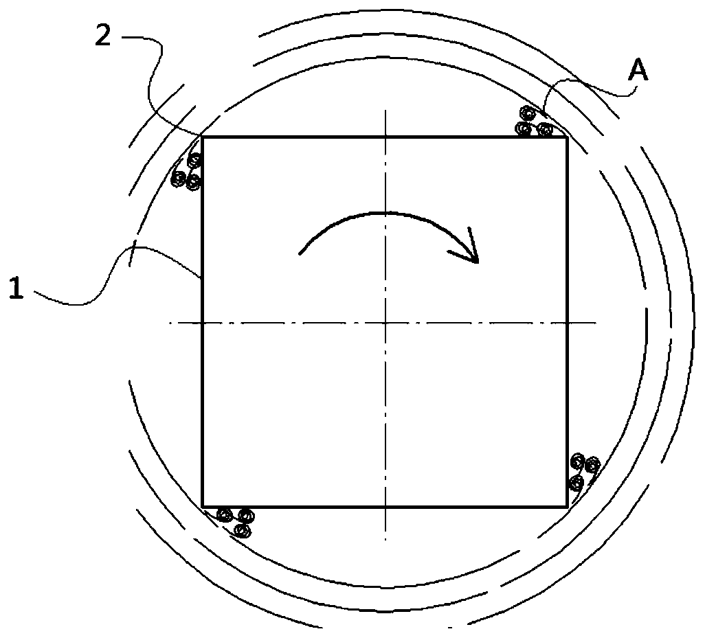
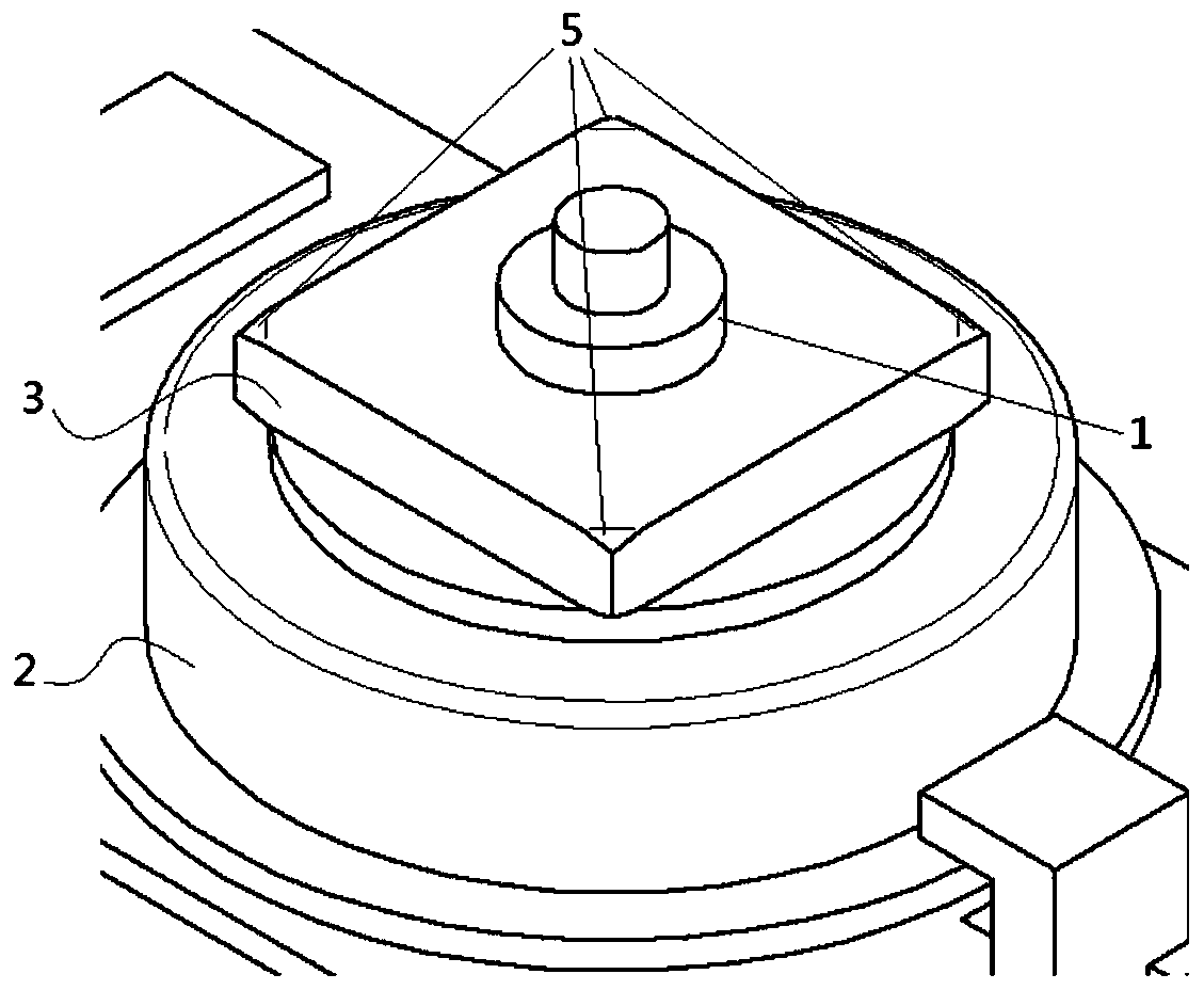
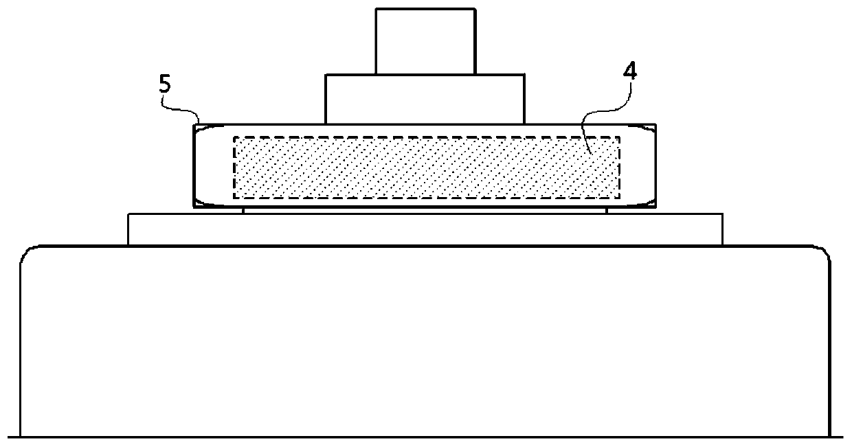
[0043] figure 2 with image 3 As shown, a polygonal mirror motor provided for the embodiment includes a rotor 1 and a stator 2 arranged around the rotor 1, and also includes: a polygonal mirror 3, which is connected to the rotor 1 and has a polygonal prism structure. There is a reflective surface 4, the reflective surface 4 is used to reflect light beams; and a guide part 5 formed on at least one side edge, the guide part 5 is used to reduce the impact on the polygon mirror 3 when it rotates. Wind resistance.
[0044] When the polygonal mirror in this embodiment rotates at high speed, the airflow near the side edge can smoothly flow through the guide part 5, which reduces the wind resistance, and the setting of the guide part 5 can make the side edge place a continuous plane or curved surface The structure avoids the obvious gap when the airflow flows through the side edge, reduces the pressure difference between the windward side and the leeward side, and prevents the form...
Embodiment 2
[0053] Such as Figure 4 with Figure 5 As shown, it is a polygonal mirror motor provided in this embodiment. Compared with the above-mentioned embodiment 1, in this embodiment, the flow guide part 5 is a curved surface extending from the side edge to the position of the vertex angle. Specifically The guide part 5 is a circular chamfer arranged along the height direction of the side edge, and the circular chamfer in this embodiment is an equal-radius rounded corner with a size of 9.25 mm. The setting of the size of the equal-radius fillet here can be optimally designed according to the boundary conditions of the reflection area 4 while meeting the size requirements of the reflection surface 4. The 9.25mm in this embodiment is based on the multi-facet Optimal implementation of the determination of the size of the mirror and the boundary conditions of the reflective surface 4.
[0054] In some other embodiments, the diversion portion 5 is a circular chamfer with a variable rad...
Embodiment 3
[0057] Such as Image 6 As shown, this embodiment provides an optical writing device, which includes the polygon mirror motor described in Embodiment 1 or 2 above, and has all the technical advantages of the polygon mirror motor.
[0058] In addition, while the optical writing device has low-noise operation, due to the setting of the guide part, the wind resistance is reduced, and the energy consumption of the polygon mirror motor A to overcome the wind resistance is reduced. The polygon mirror motor A is used as the optical writing device. The reduction of energy consumption and wear of the core drive components is beneficial to the increase of the service life of the entire optical writing device.
[0059] The optical writing device in this embodiment further includes an IC substrate, the polygon mirror motor A is fixed on the IC substrate through the motor mounting plate, and the IC substrate is used to control the operation of the polygon mirror motor.
PUM
 Abstract
Description
Claims
Application Information
 - R&D
- Intellectual Property
- Life Sciences
- Materials
- Tech Scout
- Unparalleled Data Quality
- Higher Quality Content
- 60% Fewer Hallucinations
Browse by: Latest US Patents, China's latest patents, Technical Efficacy Thesaurus, Application Domain, Technology Topic, Popular Technical Reports.
© 2025 PatSnap. All rights reserved.Legal|Privacy policy|Modern Slavery Act Transparency Statement|Sitemap|About US| Contact US: help@patsnap.com