
Flywheel bolt cap compliance detecting device and using method thereof

A detection device and bolt technology, applied in the direction of mechanical thickness measurement, etc., can solve the problem of inability to quickly detect the thickness of the bolt cap, and achieve the effects of improving detection applicability, ensuring stability and easy operation.

Pending Publication Date: 2019-06-07
Y & C ENGINE
View PDF0 Cites 0 Cited by
  • Summary
  • Abstract
  • Description
  • Claims
  • Application Information

AI Technical Summary

Problems solved by technology

[0004] The purpose of the present invention is to solve the problem that the thickness of the bolt cap cannot be quickly detected during the assembly process of the existing engine flywheel, to provide a flywheel bolt cap compliance detection device and its use method, which has the advantage of quickly detecting the thickness of the flywheel bolt cap

Method used


Image

  • Flywheel bolt cap compliance detecting device and using method thereof
  • Flywheel bolt cap compliance detecting device and using method thereof
  • Flywheel bolt cap compliance detecting device and using method thereof

Examples


Embodiment 1

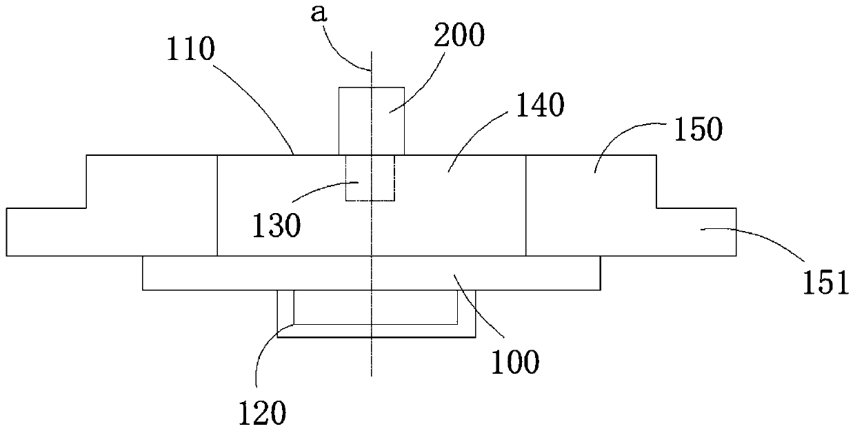
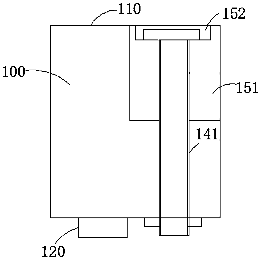
[0035] Refer to attached figure 1 and figure 2 As shown, a flywheel bolt cap compliance detection device in this embodiment includes a checker body 100, which is provided with a detection surface 110 and a hand-held part 120, and a threaded hole 130 is opened in the middle of the checker body 100. The tool body 100 is connected to the limit pin 200 through the threaded hole 130. The handle 120 and the limit pin 200 are respectively located on both sides of the test tool body 100. The axis of the limit pin 200 is perpendicular to the detection surface 110. There is a connecting end 140, and the connecting end 140 is fixedly connected to two symmetrical sliders 150. The bottom surface of the sliders 150 and the detection surface 110 are located on the same plane. Compared with standard bolts, there is not much difference in the thickness of the bolt caps, so the difference in appearance between the two is not obvious. The inspection process cannot effectively identify whether ...

Embodiment 2

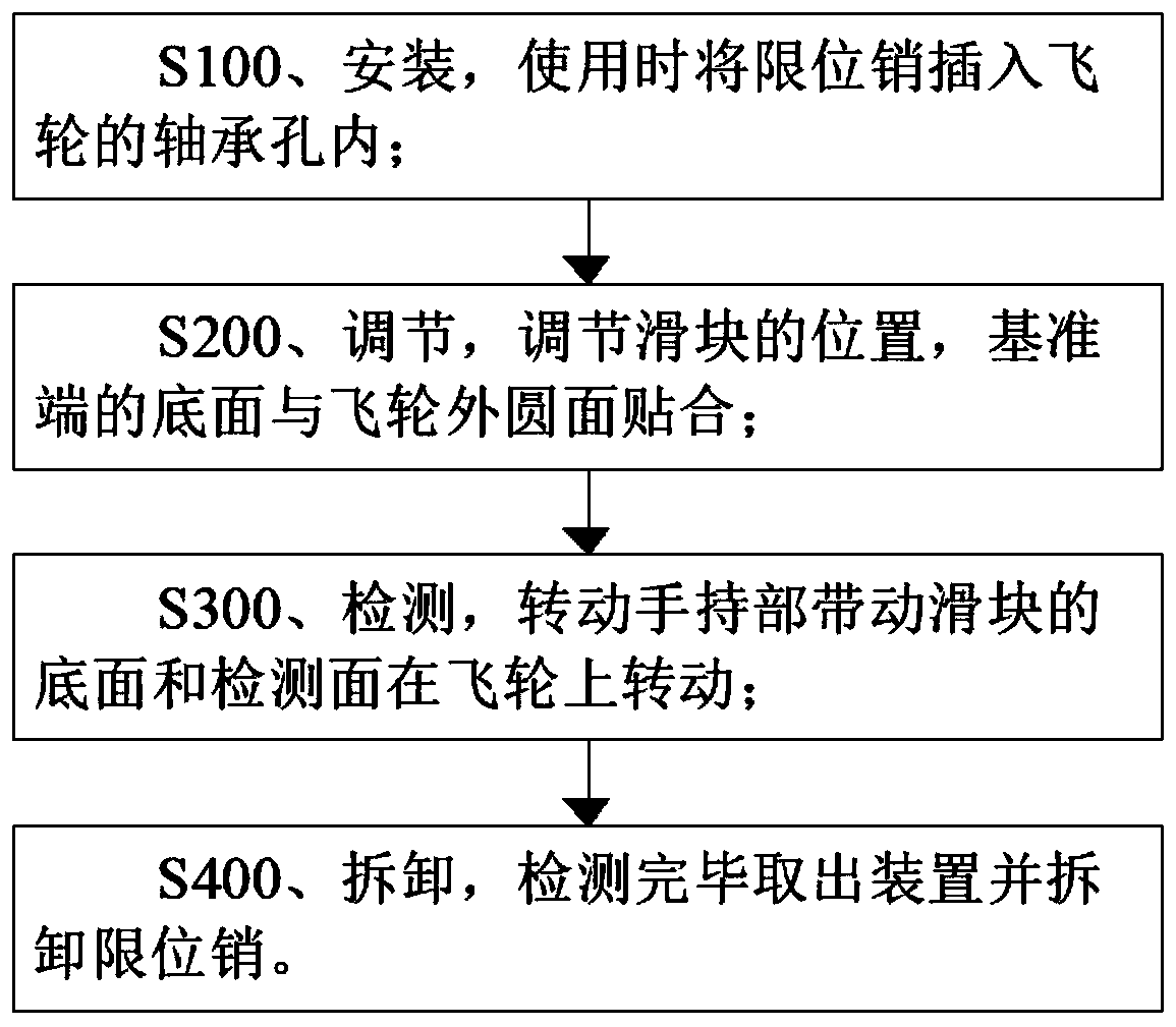
[0040] Refer to attached figure 1 , figure 2 and image 3 As shown, the use method of a flywheel bolt cap compliance detection device in this embodiment is that the bottom surface of the slider 150 and the detection surface 110 rotate around the limit pin 200 to detect whether there is interference.

[0041] The usage method of this embodiment includes the following steps:

[0042] S100, installation, when using, insert the limit pin 200 into the bearing hole of the flywheel;

[0043] S200, adjust, adjust the position of the slide block 150, the bottom surface of the reference end 151 is attached to the outer circular surface of the flywheel;

[0044] S300, detection, rotating the handle 120 to drive the bottom surface of the slider 150 and the detection surface 110 to rotate on the flywheel;

[0045] S400, dismantling, taking out the device after the detection and disassembling the limit pin 200 .

[0046] The specific method of step S200 adjustment in this embodiment i...


PUM


Abstract

The invention, which belongs to the technical field of engine fitting detecting tools, relates to a flywheel bolt cap compliance detecting device and a using method thereof. The detecting device comprises a gauge body provided with a detecting surface and a hand-held portion. A threaded hole is opened in the middle of the gauge body; and the gauge body is connected with a limit pin by the threadedhole. The hand-held portion and the limit pin are arranged at the two sides of the gauge body respectively, wherein the axis of the limit pin is perpendicular to the detecting surface. A connecting end is arranged at one side of the gauge body and is fixedly connected with two symmetric sliding blocks; and the bottom surfaces of the sliding blocks and the detecting surface are arranged at one same plane. Therefore, the thickness of the bolt cap of the flywheel can be detected rapidly and conveniently.

Description

technical field [0001] The invention belongs to the field of detection tools for engine accessories, and more specifically relates to a flywheel bolt cap compliance detection device and a use method thereof. Background technique [0002] Bolts are one of the commonly used connection parts in the automobile manufacturing industry. The cost of standard bolts is low and easy to purchase. Usually the manufacturing process will choose standard bolts. However, if the appropriate standard bolts cannot be selected according to the requirements, it is necessary to design and customize special bolts. The engine flywheel bolts have such a special situation. In order to avoid interference between the engine flywheel bolt cap and the whole vehicle, some models need to use special flywheel bolts with a thickness smaller than the standard bolt cap. Since there is not much difference in the thickness of the bolt cap between the special flywheel bolt and the standard bolt, the difference i...

Claims


Application Information

Patent Timeline
Patent Type & Authority Applications(China)
IPC IPC(8): G01B5/06
Inventor 吴家昌
Owner Y & C ENGINE
Learn More