
Electronic lock cylinder

An electronic lock and deadbolt technology, applied in the field of locks, can solve the problems of inaccurate operation control of the deadbolt, complex electromechanical composition and short service life, etc., and achieve accurate operation control of the deadbolt, low power consumption and long service life Effect

Pending Publication Date: 2019-06-07
HENAN CHUANTONG ELECTRONICS TECH
View PDF0 Cites 0 Cited by
  • Summary
  • Abstract
  • Description
  • Claims
  • Application Information

AI Technical Summary

Problems solved by technology

[0004] The technical problem mainly solved by the present invention is to provide an electronic lock cylinder, which solves the problems of large power consumption, high failure rate and long service life caused by the complex electromechanical composition structure and inaccurate operation control of the lock tongue in the prior art. Short and other questions

Method used


Image

  • Electronic lock cylinder
  • Electronic lock cylinder
  • Electronic lock cylinder

Examples


Embodiment Construction

[0026] In order to facilitate the understanding of the present invention, the present invention will be described in more detail below in conjunction with the accompanying drawings and specific embodiments. Preferred embodiments of the invention are shown in the accompanying drawings. However, the present invention can be implemented in many different forms and is not limited to the embodiments described in this specification. On the contrary, these embodiments are provided to make the understanding of the disclosure of the present invention more thorough and comprehensive.

[0027] It should be noted that, unless otherwise defined, all technical and scientific terms used in this specification have the same meaning as commonly understood by those skilled in the technical field of the present invention. Terms used in the description of the present invention are only for the purpose of describing specific embodiments, and are not used to limit the present invention.

[0028] ...


PUM


Abstract

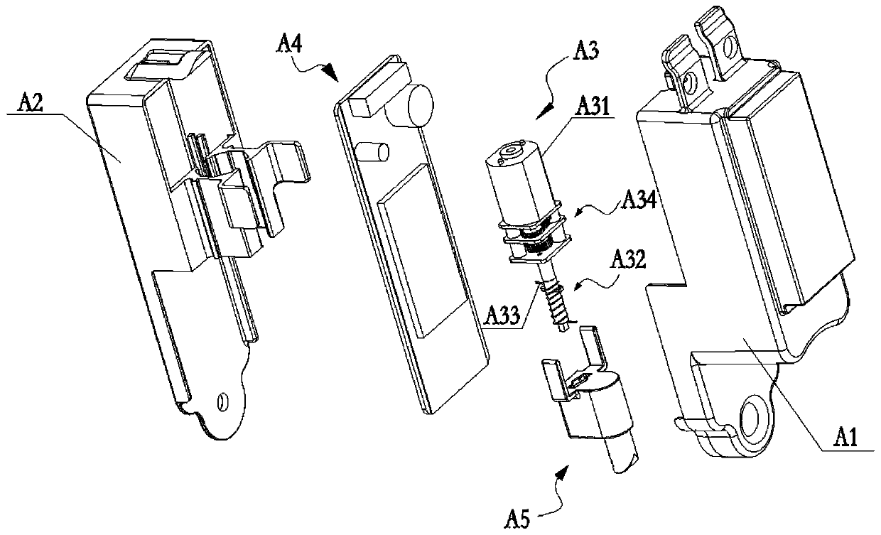
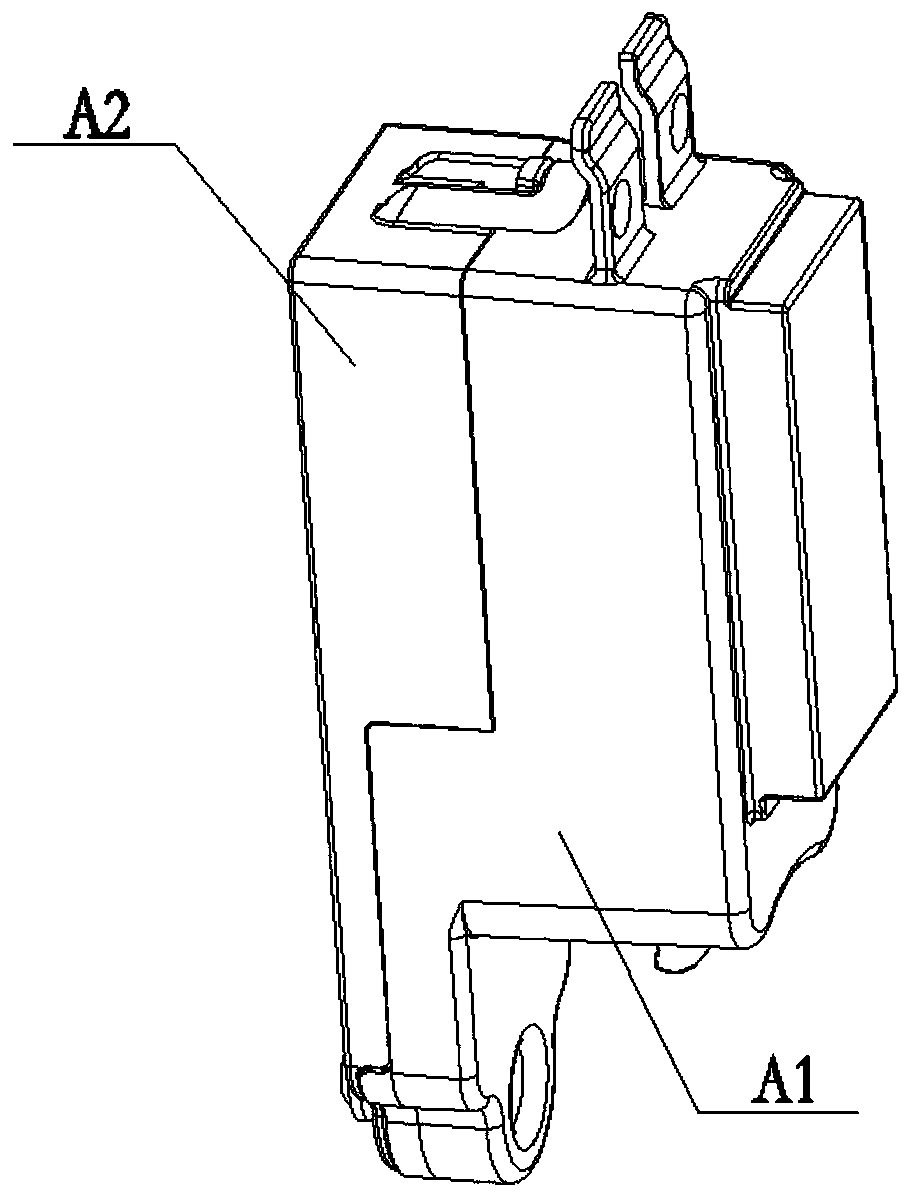
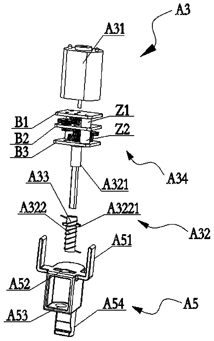
The invention discloses an electronic lock cylinder. The electronic lock cylinder comprises a shell, and a motor module, a control module for controlling the motor module to operate and a lock tonguebody connected with the motor module, which are positioned in the shell; the lock tongue body comprises a lock tongue cavity, and a lock tongue arranged at the lower part of the lock tongue cavity; and a rotating spring is arranged in the lock tongue cavity. The motor module comprises a driving motor and a rotating shaft; the driving motor is connected with the rotating shaft; and the rotating shaft penetrates through the lock tongue cavity, and sleeves the rotating spring. When the driving motor is rotated forwards or reversely, the rotating shaft is rotated to drive the rotating spring to rotationally compress or stretch; and the rotating spring is compressed or stretched to deform to drive the lock tongue body to move up and down in the axial direction of the rotating shaft so as to achieve the purposes of unlocking and locking. The electronic lock cylinder is simple in electromechanical composition structure, precise in lock tongue operation control, low in power consumption, low in fault rate and long in service life.

Description

technical field [0001] The invention belongs to the field of locks, in particular to an electronic lock cylinder. Background technique [0002] The lock cores adopted in the prior art are mainly mechanical lock cores and electronic lock cores, and the unlocking of the mechanical lock cores must be unlocked by a key, and there is a situation that the key cannot be unlocked due to the omission of the key. This problem can be avoided by using an electronic lock cylinder. [0003] In the prior art, most of the electronic lock cylinders have an integrated structure, which is difficult to disassemble and maintain, and there are many internal components, complex electromechanical structures, and inaccurate operation control of the lock tongue, resulting in high power consumption, high failure rate and long service life. issues such as short lifespan. In addition, it is also desired to provide an electronic lock cylinder with strong versatility, so as to be applicable to many diff...

Claims


Application Information

Patent Timeline
Patent Type & Authority Applications(China)
IPC IPC(8): E05B47/00E05B15/10E05B15/04
Inventor 吕建忠
Owner HENAN CHUANTONG ELECTRONICS TECH
Learn More