Magnetic charging suspension support

A magnetic charging and hanging bracket technology, applied in the machine/stand, magnet, circuit, etc., can solve the problems of troublesome pick and place, inconvenient to plug and insert charging equipment, single use function, etc., to achieve convenient pick and place, save money The effect of pick and place time

Inactive Publication Date: 2019-06-07
SHENZHEN OLIGHT E COMMERCE TECH CO LTD
View PDF5 Cites 2 Cited by
  • Summary
  • Abstract
  • Description
  • Claims
  • Application Information

AI Technical Summary

Problems solved by technology

[0002] Common mobile lighting equipment (flashlights, bicycle lights, headlamps or mobile lighting devices, etc.) The charging of lighting equipment also needs to use MricoUSB charging, which makes it very inconvenient to plug and unplug the charging equipment
Most of the existing fixed racks for mobile lighting equipment are placed on desktops and other places, and the mobile lighting equipment is placed in the fixing groove of the fixed rack, which is troublesome to take and place, and has a single function

Method used


Image

  • Magnetic charging suspension support
  • Magnetic charging suspension support
  • Magnetic charging suspension support

Examples


Embodiment Construction

[0023] Embodiments of the present invention are described in detail below, examples of which are shown in the drawings, wherein the same or similar reference numerals designate the same or similar elements or elements having the same or similar functions throughout. The embodiments described below by referring to the figures are exemplary and are intended to explain the present invention and should not be construed as limiting the present invention.

[0024] In describing the present invention, it should be understood that the terms "length", "width", "upper", "lower", "front", "rear", "left", "right", "vertical", The orientation or positional relationship indicated by "horizontal", "top", "bottom", "inner", "outer", etc. are based on the orientation or positional relationship shown in the drawings, and are only for the convenience of describing the present invention and simplifying the description, rather than Nothing indicating or implying that a referenced device or element...


PUM


Abstract

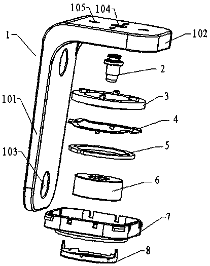
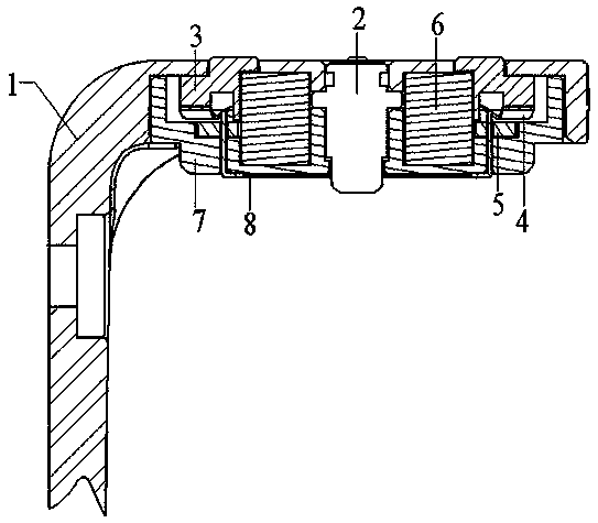
The invention belongs to the field of movable lighting equipment, and relates to a magnetic charging suspension support. The magnetic charging suspension support includes a support main body, a magnetis arranged inside the support main body, and a positive pole probe and a negative pole assembly are mounted on the support main body; the negative pole assembly includes a negative pole contact piece, a negative pole conductive ring and a negative pole elastic piece, wherein the negative pole contact piece is arranged at one side of the support main body, the negative pole conductive ring is arranged at the side, away from the negative pole contact piece, of the support main body, and the negative pole elastic piece is arranged between the negative pole contact piece and the negative pole conductive ring, the negative pole contact piece is connected with the negative pole conductive ring, and the negative pole contact piece is further connected with a PCB; the positive pole probe includes a first positive pole contact point and a second positive pole contact point which are elastically connected, wherein the first positive pole contact point is exposed at one side of the support mainbody, and the second positive pole contact point is exposed at the side, away from the first positive pole contact point, of the support main body. By adopting the magnetic charging suspension support, the movable lighting equipment can be easily taken and placed, and the occupied space is small; meanwhile, power transmission can be achieved, and thus the movable lighting equipment is convenientto charge.

Description

technical field [0001] The invention belongs to the technical field of mobile lighting equipment, and relates to a magnetic charging suspension bracket. Background technique [0002] Common mobile lighting equipment (flashlights, bicycle lights, headlamps or mobile lighting devices, etc.) Charging the lighting equipment also needs to use MricoUSB charging, which makes it very inconvenient to plug and unplug the charging equipment. Most of the existing mobile lighting fixtures are placed on desktops and other places, and the mobile lighting fixtures are placed in the fixing slots of the fixtures, which is cumbersome to take and place, and has a single function. Contents of the invention [0003] The object of the present invention is to address the shortcomings of the prior art and provide a magnetic charging suspension bracket to facilitate charging and quick pick-and-place of mobile lighting equipment. [0004] In order to achieve the above object, the present invention...

Claims


Application Information

Patent Timeline
Patent Type & Authority Applications(China)
IPC IPC(8): A47G29/08
CPCH01F7/0252H02J7/0044F21L4/08F16M13/02F16M11/041H02J2310/40F16M13/06H02J7/0042
Inventor 范江
Owner SHENZHEN OLIGHT E COMMERCE TECH CO LTD
Why Eureka
Try Eureka