


Quick Research
Generate reliable direction feasibility study reports for your R&D in just a few steps.

Technical Q&A
Discover and master advanced knowledge NOW. Basics, ideas, possibilities, all at once.

Find Solutions
As an expert in R&D theories, this can generate solutions to your technical problems instantly.

Evaluate Feasibility
Analyze your overall solution with one click, know your potential R&D risks in advance.

Monitor Landscape
Get weekly tech updates, stay abreast of the latest tech innovations and key insights.
Conduit of a tank arrangement, and tank arrangement of a vehicle
A pipeline and component technology, applied in the field of plastic pipelines and vehicle tank components, can solve the problems of connection damage, impossible to achieve reliable attachment of return pipelines, etc.
- Summary
- Abstract
- Description
- Claims
- Application Information
AI Technical Summary
Problems solved by technology
Method used
Image


Examples
Embodiment Construction
[0027] Refer below Figures 1 to 9 The box assembly 1 according to a preferred embodiment of the present invention is explained in detail.
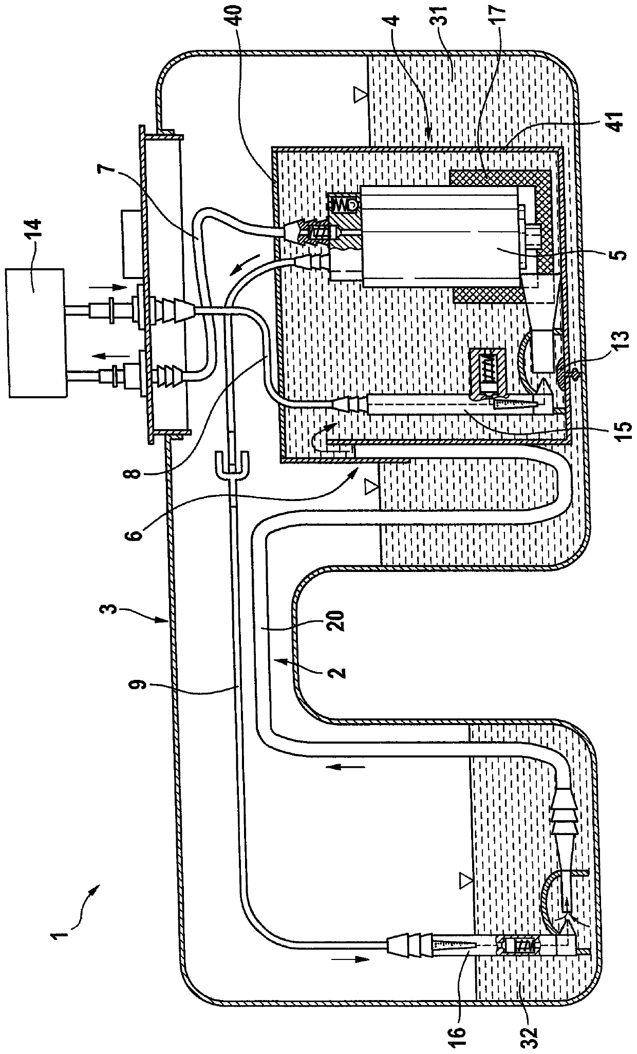
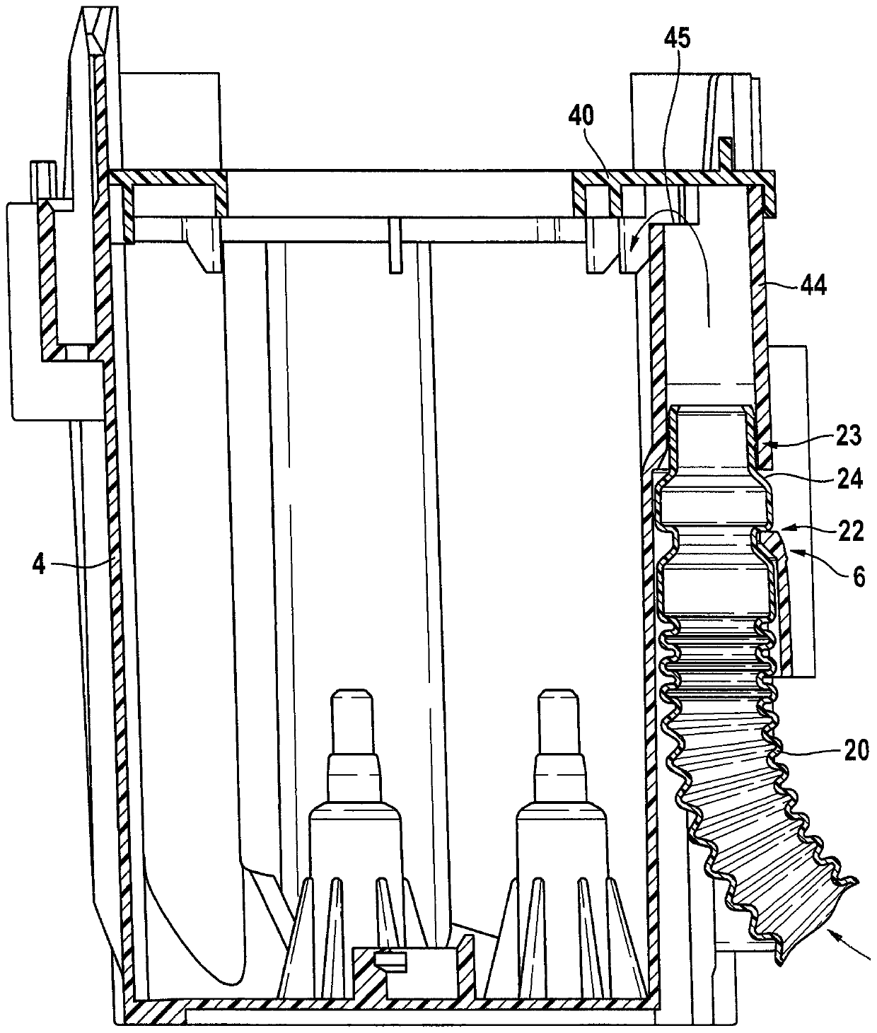
[0028] The tank assembly 1 comprises a tank 3 in the form of a saddle tank having a first tank chamber 31 and a second tank chamber 32 which are interconnected. In the first tank chamber 31 is arranged a storage tank 4 in which a pump 5 is installed. The storage tank 4 comprises a tank-shaped base body 41 which is closed by means of a lid 40 .
[0029] The storage tank 4 is filled with fuel from the first tank chamber 31 via the filling valve 13 . A first line in the form of a delivery line 7 leads from the pump 5 in order to deliver fuel to the internal combustion engine 14 . Fuel not consumed in the internal combustion engine is led back into the storage tank 4 via the return line 8 . In this case, the return line 8 leads to a first suction jet pump 15 which conducts the fuel to the pump 5 via a filter 17 .
[0030] Arranged in the...
PUM
 Abstract
Description
Claims
Application Information
 - R&D Engineer
- R&D Manager
- IP Professional
- Industry Leading Data Capabilities
- Powerful AI technology
- Patent DNA Extraction
Browse by: Latest US Patents, China's latest patents, Technical Efficacy Thesaurus, Application Domain, Technology Topic, Popular Technical Reports.
© 2024 PatSnap. All rights reserved.Legal|Privacy policy|Modern Slavery Act Transparency Statement|Sitemap|About US| Contact US: help@patsnap.com